Category Archives: Tech

Ubuntu 24!

Introduction

My home desktop has been running Ubuntu 18 since it came out in April 2018. As all even numbered versions, it has LTS (long term support) for 5 years, which ended last year. Yet the reliability of Ubuntu is a double edged sword. It runs so long, without filling the hard drive with garbage, without fragmenting the filesystem, without losing performance, that over the years you customize it so many ways that by the time you need to upgrade, it’s hard to remember everything you’ll need to set up in a new system.

So why upgrade at all? After 5 years there are no more updates. No more security patches, and for most of the applications you can only run old versions. So you need to upgrade to use the latest versions of applications and stay on top of security.

You can upgrade in place to keep everything you’ve configured, with do-release-upgrade. But this only takes you up 1 step to the next LTS version (18 to 20, 20 to 22, etc.). So I’d have to do that 3 times! And it doesn’t guarantee that everything you set up will work – though it usually does.

This time around, 6 years and 3 versions behind, I decided to do a full upgrade from 18 to 24 and wipe the system boot drive. I waited until Ubuntu 24 was released on April 25 and then hit the keyboard.

Install

I actually use XUbuntu, a variant of Ubuntu that uses the XFCE desktop instead of Unity. I prefer the XFCE desktop, as it is more traditional and faster, using less CPU and RAM. Even if the computer is fast enough to support a more heavyweight desktop, why waste the CPU and RAM on that? Even if Unity was as lightweight and fast as XFCE, I would still prefer XFCE.

First I backed up my system using deja-dup. Most of my data files are on separate hard drives, which I would not be erasing. So I only needed to back up my home directory and an “apps” directory that I use for software that is manually installed. I also reviewed my apps and files to ensure that all the software I wanted to install was available on my data drive: DEB, TAR, etc. As my desktop has 4 drives, I wrote down the device and UUID for each so I could recognize them during installation.

Next I downloaded the ISO file, burned it to a DVD, rebooted to the DVD which started XUbuntu. I selected to do a manual install, reformatting the system drive. I selected “minimal installation” because I didn’t want a bazillion crapplets that I’ll never use, but also “include 3rd party and binary software”. This all went smoothly and it also automatically installed the NVidia drivers for my GTX1660.

Next, I removed the DVD and booted, my computer came up in XUbuntu 24. Yay! But now the real work begins…

Configuration

Firefox

Firefox is a mess in Ubuntu 24. First, by default it installs as a Snap, which nobody likes. And, on top of this, they’ve crippled its access to the filesystem. You can remove it from Snap with snap remove firefox and then install with apt install firefox, but the next time you update it will revert back to the Snap install. To get it to stay this way you’ve got to edit some config files to tell the system to always install it from apt.

Next, I found that Firefox could not download files. After scratching my head for a while I realized this is because my home Downloads folder is a link that points to my data disk. And I also discovered that I could not open local documentation HTML files for the Android and Java SDK. Putting 2 and 2 together, I realized that someone decided to cripple Firefox’s access to the filesystem. WTF!?

I suspect this is the “younger generation” of developers, who think the local filesystem is somehow “unsafe”, and really unnecessary anyway since they do everything in the cloud. That is the only reason I can imagine for the crazy idea of crippling such an essential function. Most sites say that installing Firefox from apt instead of Snap solves this. Perhaps it once did, but not anymore in Ubuntu 24. With some Googling I learned they’ve created an AppArmor config that restricts filesystem access for Firefox. My fix was to configure AppArmor to disable the Firefox controls, like this:

sudo ln -s /etc/apparmor.d/usr.bin.firefox /etc/apparmor.d/disable

Altogether, this got Firefox working properly again.

Backups: Deja-Dup and Duplicity

To restore all of my backups I’d have to be root because some of the files to be restored are system, owned by root not by me. No problem, right? Think again. My backups are on a separate disk that I mount to a local folder /dsk3. When I ran deja-dup to restore a backup, it would unmount that drive!

If I ran deja-dup as myself, it would work only because it wasn’t root so its attempt to unmount the drive would fail. This was fine, it still worked, even if only by accident. But with deja-dup it is impossible to restore a backup that you have mounted to a separate disk, if you run it as root.

I could not find a solution to this, so I only restored my home and apps directories mentioned above. That’s all I really needed to back up, so I got lucky.

Thunderbird

I installed from apt and it saw all of my email that was restored from the backup – both my local folders and all of my IMAP email server accounts. Bang!

Python and Virtualenv

In Ubuntu 24 Python works differently. The system Python is now 3.12 instead of 2.7, which is nice. But the procedure for installing virtualenv and virtualenvwrapper that I used for Ubuntu 22, does not work in 24.

First, use pipx instead of pip. That is, pipx install virtualenv.  After that, pipx install virtualenvwrapper. At this point they are installed but the don’t work. Next, I had to change the environment variables and python & wrapper script locations:

export WORKON_HOME=$HOME/.virtualenvs
export VIRTUALENVBIN=$HOME/.local/share/pipx/venvs/virtualenvwrapper/bin
export VIRTUALENVWRAPPER_PYTHON=$VIRTUALENVBIN/python
source $VIRTUALENVBIN/virtualenvwrapper.sh

I created some virtualenvs, listed them, etc. it all works fine – great!

Pulseaudio and Pipewire

Ubuntu 24 audio is working, but it runs pipewire instead of pulseaudio. I had pulseaudio configured to avoid resampling for bit perfect audio. Pipewire is not doing this; it resamples everything to the system default sample rate of 48 kHz. With some reading, I found a simple way to configure this.

The pipewire config files reside here: /usr/share/pipewire

In particular, the primary config file is: /usr/share/pipewire/pipewire.conf

But rather than edit this directly, you can leave it in place there and create another config file that overrides individual settings.

Create this directory if it doesn’t already exist: /etc/pipewire/pipewire.conf.d

And in that directory, create text files (having any name) that override individual settings. For example I created this file: /etc/pipewire/pipewire.conf.d/pipewire-custom.conf

# Daemon config file for PipeWire version "1.0.5" #
#
# Copy and edit this file in /etc/pipewire for system-wide changes
# or in ~/.config/pipewire for local changes.
#
# It is also possible to place a file with an updated section in
# /etc/pipewire/pipewire.conf.d/ for system-wide changes or in
# ~/.config/pipewire/pipewire.conf.d/ for local changes.
#

context.properties = {
    ## Properties for the DSP configuration.
    default.clock.rate = 48000
    default.clock.allowed-rates = [ 44100 48000 88200 96000 176400 192000 ]
}

stream.properties = {
    resample.quality = 10
}

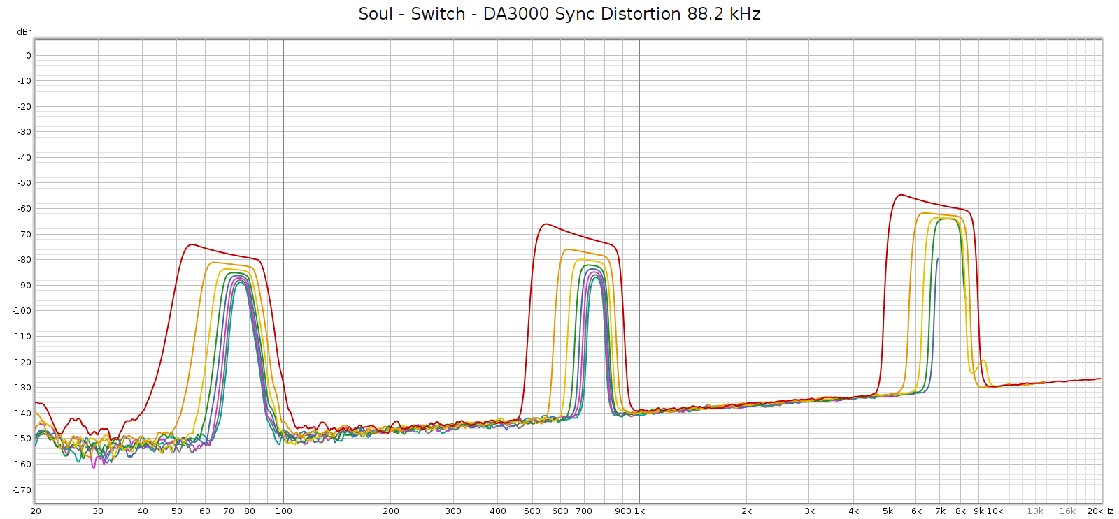
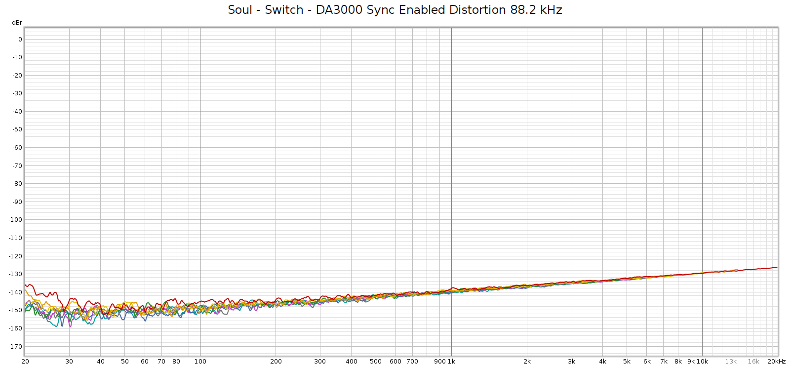
After doing this, when I play audio files using VLC, with an external DAC connected to my sound card’s SPDIF output, the external DAC shows the sample rate changing to the native sample rate of each file that I play. It works!

Also: the DSP library PulseEffects was replaced with EasyEffects, a newer version that works with PipeWire. This new version has a feature I like: it does not resample all audio to the system sample rate like PulseEffects did, but plays audio at its native rate without resampling, changing the system rate to match the audio. Very nice!

Audio Update

Audio stopped working on each bootup. After some troubleshooting I discovered that the kernel module for my Juli@ sound card is not loaded. How to check this?

First, run lspci -k and it shows you all your PCI cards, and for each, which kernel module it uses. This tole me the card is plugged in and the module is snd_ice1724.

Next, check whether that module is loaded, or really check for all sound modules by running: lsmod | grep snd_. This did not list the snd_ice1724 module.

So, load the module manually by typing: sudo modprobe snd_ice1724. After that, repeat the above command to see if it’s loaded. Bingo! It was. And after doing this, audio started working.

Now here’s the mystery: normally you can tell the system to load new kernel modules by creating files in files in /etc/modules.load.d. For example I created this file:

-rw-r--r-- 1 root root 53 Apr 29 18:02 /etc/modules-load.d/snd_julia.conf

The contents are simple:

# kernel module for the Juli@ sound card
snd_ice1724

This should tell Linux to load the module at boot, so I don’t have to load it manually. But my system still doesn’t load this module. Or maybe it’s trying but failing, but I can’t find any errors. And I also looked for it in blacklists, but it is not a blacklisted module. Indeed, if it were the system shouldn’t let me load it manually.

At least I can fix the problem, but I don’t know why it doesn’t load automatically when it detects the sound card, nor manually from the config file, so I’m stuck loading this module manually at the command-line.

Java, Tomcat and PostgreSQL

I installed openJDK versions 8, 11 and 21, using apt, then ran update-alternatives to set the default to JDK 8. Even though it’s old, a lot of software requires it and won’t run on the newer JDKs.

Next I installed Tomcat, version 10 is what comes with Ubuntu 24. That was simple enough.

Then I needed the PostgreSQL JDBC driver so my Tomcat server could talk to databases on other servers in my home network. I found the JAR file online, copied it to /usr/share/java and linked it to /usr/share/tomcat10/lib.

Finally, I copied my audio recordings JSP app to Tomcat. First I made a directory for the app: /var/lib/tomcat10/webapps/audiorec. Then I copied the source files (JSP) to that directory. BANG! It just worked.

Apps and Games

I installed Steam and after configuring it, it saw all of my games on my separate disk drive. And it saw my configs since I restored my home directory. All good? Nope.

Two games I’ve been playing recently are Valheim and Bioshock Infinite. Steam showed how long I had been playing and when I most recently played. And the games are supposed to save your progress in the cloud. But when I started the games, they started from scratch. They had no notion of any prior game play or saves. I lost all my progress in the games.

On the brighter side, the games now run natively in Linux, where previously with Ubuntu 18 they only ran reliably from Proton, the Windows emulator. Same hardware, same drivers, the only difference is Ubuntu 24 versus 18. So I don’t know why, but that is nice…

Printers and Virtualbox

Back in 2019 I bought the TurboPrint driver for my Epson SureColor P400 printer. This is a good thing, since Epson doesn’t have a Linux driver for this printer – even though they do for most of their other models. Yet the TurboPrint driver installed and worked just fine, it doesn’t need the Epson driver. Turboprint is excellent, and essential for anyone who wants to print photo quality from Linux.

I have a Windows 10 VM for software that doesn’t run on Linux. Just a couple of apps, Epson’s CD print and Suunto’s link for my GPS wristwatch. I installed virtualbox simply from apt and it just worked – my VM came up just fine. Of course I did have to edit my system groups to ensure that I am in both plugdev and vboxusers in order for the Windows VM to be able to see USB devices like the printer and the watch.

Addendum: IOMMU

What the heck is IOMMU, you might ask? Indeed, I asked the same. I noticed a bunch of errors in dmesg, like this:

DMAR: DRHD: handling fault status reg 3

With some Googling I found it is related to a CPU chip function related to RAM called IOMMU. I’ve been using Linux since Ubuntu 8 in 2009 on a wide variety of desktops and laptops, and I’ve never seen this before. Maybe this desktop’s CPU is too old to support it – it’s an i7-4770 from around 10 years ago. Still reliable & fast, so why replace it?

The solution was to add a kernel boot parameter iommu=soft. I did this by editing the /etc/default/grub file, then running update-grub. Confirmed fixed.

Note that if I set this parameter to iommu=off, the USB system doesn’t work. No keyboard, no mouse, connect via SSH and lsusb reports no devices.

Conclusion

Of course there was a bunch of other stuff. And I’m not even done yet. But the computer is mostly working again, with most of my data and apps restored. I’ll get the rest of it working over time.

Email Send, IP Addresses, Blacklisting

About a month ago emails that we sent were bouncing, being rejected by the destination servers saying one of the IP address where it came from was blacklisted. I host this site and our email through Hostgator, using their SMTP server to send email. So my first guess was that the Hostgator SMTP server was blacklisted. It’s plausible, as it’s shared by many customers, some of whom may be spammers. But the IP address from the email bounce message didn’t match that server. Turns out it was the IP address that Comcast assigned to my home router. So Comcast assigned me a blacklisted IP address! Perhaps Comcast shares that IP with other customers and one of them has been spamming.

However, email sent from my GMail SMTP was not bouncing. Looking at the email headers, GMail’s SMTP does not forward the IP address of the client who sends it; it sends its own. So one possible solution would be to get the Hostgator SMTP to stop forwarding my IP address, but instead use its own, or even use my own IP address for this domain, mclements.net. I contacted Hostgator support and they said they could not configure the SMTP server to do this.

In the meantime, as a temporary workaround I configured my email send to use the GMail SMTP and CC my other email. It’s clumsy but works.

My next option was to change my Comcast IP address. I called support and they confirmed that Comcast uses DHCP, so getting a new IP address should be as simple as turning off my modem & router, then turning them back on. I knew it wasn’t that simple because I had done that and the IP address never changed. The DHCP has a lease with a time duration. You need to disconnect long enough for that to expire before getting a new IP address. I left them off overnight and still got the same IP address.

DHCP servers often (though not always) use the client MAC address as a hash when providing IP addresses. If you can change the MAC address of the router that connects to your cable modem you are likely to get a new IP address. I dug into my router menus and found a config option to do exactly this: you can enter any MAC address you want, or have it copy the one from the PC you are using to connect to the router. When setting MAC addresses manually like this, one must be careful because the MAC address is not just a random number. The first several hex codes are assigned to manufacturer and device type. You should ensure that what you enter is a valid MAC address.

In short, this worked. After changing my router’s MAC, Comcast issued a different IP address that was not blacklisted, and now my email is not bouncing. Since these IP addresses belong to Comcast, I called to let them know the old IP address was blacklisted so they can deal with it.

Summary of steps:

  1. Configure your router to use a different MAC address
  2. Turn off the cable modem and router
  3. Turn on the cable modem and let it boot up and sync
  4. Turn on the router

After step (4) it may take longer than usual to get an internet connection. When the router negotiates with Comcast for a connection, if its MAC address is different and Comcast assigns a new IP address, the process can take longer.

Tascam DA3000

The Tascam DA-3000 is a professional rack mount digital recorder. For years I owned a prior model, the SS-R1. It provided years of reliable service and I used it to archive nearly 1,000 vinyl LPs. The DA-3000 improves upon the SS-R1 in a few important ways:

  • Better AD converters: Burr Brown PCM4202
  • Better DA converters: Burr Brown PCM1795
  • Supports higher data rates: 24 bit, up to 192 kHz PCM and DSD 128 (5.6 MHz)
  • Direct AD-DA mode
  • Lower distortion and noise

It also retains many of the most important features of the SS-R1

  • Records to SD and CF media (no internal hard drive)
  • No fans – dead silent
  • The flexibility of many connections
    • Analog unbalanced RCA input and output
    • Analog balanced XLR input and output
    • SPDIF coax input and output
    • AES/EBU input and output
    • Internal or external clocks
  • Professional build quality, durability and reliability

Tascam no longer makes the DA-3000 so I bought mine used from eBay. In using it I’ve discovered some interesting quirks.

Date/Time Clock

The SS-R1 had a clock that had to be set every time you powered it on. Even when plugged in, it would forget the date & time when turned off. The DA-3000 fixed this – at least supposedly. But every time I powered mine up, I had to set the clock.

The problem was that the DA-3000 uses a rechargeable button cell battery to remember the clock when turned off. And it uses a tiny one that is soldered to the board. After a year or two, this battery dies and is not easy to replace (you must disassemble the unit, remove the board and solder). I contacted Tascam support and they said they no longer provide this service. It was annoying enough I decided to do my own permanent fix, better than what they would do at the factory.

Rather than simply replace that soldered-in battery, I installed a small battery cage for a CR2032 battery, which has the same voltage but is more than twice the size and capacity. Instead of soldering a new battery onto the board, I soldered the battery cage lead wires. Here’s what it looks like now:

I put an ML2032 battery into the cage (the rechargeable version of a CR2032). Not only will it last much longer than the tiny OEM battery, when it dies I can now replace it in 10 minutes easily without any soldering. This is how the DA-3000 should have been built from the factory.

DA-AD Mode

This mode stands for “Digital-Analog, Analog-Digital”. In this mode, the DA-3000 doesn’t record, but merely activates its DA and AD converters. You select which analog & digital inputs & outputs it uses. The DA converter has a slightly warm, soft voicing free of glare. Very nice. I can find no explanation for this in measurements, as its frequency response and distortion measure clean.

DA-AD mode does not auto-detect the sample rate. You must select the sample rate in the menus. If the sample rate you select does not match the digital input, the DA-3000 will still produce analog output but it is distorted. By this I mean high frequencies rolled off with elevated harmonic distortion.

Frequency response in DA-AD mode with sample rate mismatch, compared to sample rate match.

Distortion in DA-AD mode with sample rate mismatch:

For comparison, here’s distortion when you manually set the rate to match the input:

This distortion is measured after the DA3000 DA conversion and the SSR1 AD conversions. The distortion when you don’t manually set the sample rate to match the input is not documented in the manual, and Tascam support did not respond to my inquiry about this. So just know about this and set it!

Sample Rate Sensitivity

The popular S/PDIF digital format (whether coax or toslink) is a “push” protocol. The source device sends data to the downstream target using the source’s clock. The target device has no way to tell the source to slow down or speed up. No two clocks ever agree exactly, so the target device has to adapt to the source device sample rate. In contrast, audio over USB is a “pull” protocol. The downstream target device runs off its own clock, requesting data from the source as needed. No need to synchronize clocks or adapt sample rates.

Lest anyone disregard S/PDIF clock sync as a problem “solved in the real world”, consider that well engineered DACs use TCXO for their clock, which are temperature compensated crystal oscillators. These are typically accurate to roughly 1 ppm, which at CD quality 44.1 kHz makes a clock drift of 1 sample every 22.6 seconds. So the issue is real – with S/PDIF, the downstream device must adapt to the upstream clock. Buffering can’t entirely solve this, because it can only solve variations around an identical center frequency. Put differently, no two devices will ever agree on the center frequency, one will always be slightly slower than the other, which means any buffer you use will eventually under/over flow. With S/PDIF the downstream device must not only buffer the data, but also adapt its clock to the source rate.

The Tascam DA-3000 specs say it can sync to any input digital sample rate within a range +/- 100 ppm. This should be plenty, about 100x greater than the drift expected from a well engineered DAC. However, in my setup I have a toslink-coax converter between my Corda Soul (preamp/DAC) and the DA-3000. This converter causes quite a bit of jitter, so much that the DA-3000 occasionally loses sync. For example, a REW frequency sweep played through the Soul and captured on the DA-3000 looks like this:

That capture was at 88.2 kHz sampling, but it happens at all sample rates. My Topping E70 DAC handles this jitter just fine and is super clean, because it has a setting called DPLL that controls how much sample rate variance it can accept and adapt to. I had to bump it up a couple of notches to handle the switchbox.

Fortunately, the DA-3000 can do the same thing, even though one method for doing it is undocumented. When recording, enable SRC which is Sample Rate Conversion. This won’t actually convert the sample rate, because you’ll still manually set the DA-3000 sample rate to match the digital input. But when SRC is enabled, the DA-3000 accommodates and adapts to a wider range of jitter.

A better, cleaner method is to change the DA3000 clock setting from “Internal” to “DIN”. This tells the DA3000 to use the digital input as its own reference clock.

When you do either of these, distortion in the REW sweep is super clean like it should be:

AD Converter HF Noise

Another quirk of the DA-3000 is super high frequency noise in its AD converter. The noise is at 100 kHz, so you won’t see it at sample rates of 96k and lower since it’s above the Nyquist frequency. But at 176.4 and 192 kHz, it is there and looks like this:

So, if you are recording from analog inputs, don’t use 176.4 or 192 kHz. Use 88.2 or 96 kHz instead. The sound quality will be better! This is not an issue if you are recording digital inputs – that is just a bit perfect copy.

Analog Output Level

Normally, a recorder’s analog output level isn’t that important. But when using the DA-3000 in AD-DA mode, it becomes so. You need to match the input voltage sensitivity of the downstream preamp. The DA-3000 has a setting called “Reference Level” that sets this. Indirectly, this sets the analog output voltage for digital peak levels. The range is -9 dB which is +15 dBu (quiet) to -20 dB which is +24 dBu (loud). In Volts RMS this ranges from 4.36 to 12.28. The first is the consumer audio standard, the second is the professional standard.

Most consumer preamps have voltage sensitivity for their balanced analog inputs that expects peak levels around 4 V. Higher voltages can cause them to clip or distort. So you would set the DA3000 to -9 dB.

The Corda Soul has an internal switch to set its analog input voltage sensitivity. The default setting is for professional audio, expecting 12 Volts (low gain). Flick the switch to the other position and it changes to consumer, expecting 4 Volts (high gain). With the Soul set to low gain, the DA3000 setting that matches the output level of the Soul’s internal DAC is -16 to -18: -16 is about 0.5 dB quieter and -18 is about 1.5 dB louder.

Conclusion

The Tascam DA-3000 is a wonderful recorder. It is incredibly flexible, easy to use, with SOTA transparent sound quality and professional build quality. It has many other features not described here, since I’ve focused on its quirks. I’ve wanted one for years and I am so happy I finally found it!

Like any piece of gear, it has a few quirks as seen above. But none of these are serious problems, they all have workarounds.

Electronic Gyro Drift Correction

Introduction

A magnetic compass is still a required navigation instrument in airplanes. The most common type is called a “whisky compass”, mounted at the top center of the panel. The compass is tilted toward the pilot to make it easier to read. Yet this also makes it accurate only in straight and level flight. When turning, the compass’ balance masses and tilt make its reading lead or lag the airplane’s actual heading.

Most airplanes also have a directional gyro. The gyro’s rotational inertia keeps it in a stable position as the airplane rotates around it. This means it reads accurately when turning. But gyros slowly drift over time. This means during straight and level flight, the pilot must occasionally check the gyro and manually set it to the compass heading. How often is occasionally? Depends on the gyro. For gyros that are entirely independent having no external correction, it’s about every 15 minutes. And this is true whether it is mechanical or electronic.

Gyro Drift

Gyro drift is caused by two factors: the rotation of the Earth, and friction (for mechanical) or noise/errors (for electronic).

The Earth rotates through 360* every 24 hours, which is 15* per hour. The gyro is immobile in space independent of the Earth’s rotation. Thus as the Earth rotates, the gyro “moves” relative to the Earth, and since the Earth is our frame of reference, this causes the gyro to drift. The relative motion of the Earth can make a theoretically perfect gyro drift up to 15* per hour from the pilot’s frame of reference.

Bearing friction and electronic noise are more intuitively obvious causes of gyro drift. With electronic gyros we have the advantage of being able to apply software corrections. Electronic gyros are based on accelerometer sensors, which means the sensor readings must be mathematically integrated to get position. Integration cumulatively amplifies small sensor errors. For example, even if the sensor’s readings consistently average the correct value over time, each individual reading will be slightly more or less. And these accumulate over time into increasing errors.

Drift Correction

One form of drift correction is when the pilot sets the gyro to match the compass heading. Immediately after this we can assume the gyro’s heading is correct. If we store each of these changes, we have a history of how much the gyro has been drifting and can use that to auto-correct and reduce drift.

Correcting this automatically applies only to electronic gyros, since we need a software algorithm to compute and apply this.

Bias and Variance

Errors and noise fall into two categories: bias and variance. Bias refers to anything systematic or predictable, variance is the unpredictable random portion of the errors. We can detect and correct for bias but not for variance. We must be careful, because misinterpreting variance as bias can increase errors rather than reduce them.

The basic idea is that after each pilot correction, we compute the rate of drift of the correction and continue to apply that to the gyro going forward. For example, if the most recent correction was +10* and it was made 15 minutes after the prior correction, the correction is +0.667* per minute, so we automatically apply that to the gyro going forward.

However, it’s not quite that simple so the idea needs refinement.

For example, suppose the drift that the pilot is correcting reverses direction each time. In this case, if we correct as above, we would actually amplify rather than reduce the drift, making things worse rather than better.

The problem is that errors are a mix of bias and variance, yet our idea only works to reduce bias, not variance. One simple way to differentiate bias from variance is to look at whether recent user corrections all go in the same direction. When this happens, there is a simple linear component to the gyro errors: it’s consistently drifting in the same direction, whether clockwise or counter (this is not the only form of bias, but it’s the simplest and easiest to detect). Yet even a blind squirrel sometimes finds a nut, and random errors will sometimes also go in the same direction. When you flip a coin, you will sometimes get heads several times in a row.

Consider that with variance (completely random errors), each pilot correction is 50% likely to be in either direction, like flipping a coin. If you flip a coin twice, you get 2 heads or 2 tails half the time. Similarly, with pure variance and no bias, about half the time each pilot correction will be in the same direction as the prior correction. Three consecutive corrections in the same direction would happen about 25% of the time. Conversely, we can say that in this case the error is 75% likely to have some bias.

So we should not apply our automatic correction unless the most recent N pilot corrections were all in the same direction, and N should be at least 3. Also, we should shrink the auto-corrected rate accordingly. For example when N=3 the error is 75% likely to have some bias, but it will always have some variance too. So let’s assume that 75% of the error is bias and shrink the correction applied going forward to 75% of the pilot-entered value. In the above example, the +0.667* per minute becomes 0.5* per minute.

Oscillation and Damping

At this point we have a simple algorithm that should improve the gyro accuracy. Yet we can improve it further without adding complexity. The idea is that our method to discern bias from variance is always imperfect, and if we get it wrong it makes things worse, not better. It is better not to correct errors, than to make them worse. Put differently, if we are too aggressive with error correction we can make things worse, while if we are too passive or conservative, it still improves things just not as much.

So, we will apply a damping factor to our corrections, shrinking them just a bit. Pick a constant scaling factor between 0.0 and 1.0 and apply that to the correction. For example, suppose we pick 0.85 or 85% and N=3. With the above example, suppose the last 3 pilot corrections were all in the same direction, and the most recent one was +10*, and it was made 15 minutes after the prior one.:

  • The raw error being corrected is 10* / 15 minutes = 0.667* / minute.
  • Because N=3 we are 75% confident there is bias in this error, so shrink it to 75% of its value.
  • Apply our damping factor of 85%.
  • This makes the auto-correction factor 0.667 * .75 * .85 = 0.425* / minute
  • Apply this rate correction automatically going forward

Overall, we end up with a single pilot correction rate that is maintained in cumulative fashion. For example, in the last step above we don’t just set it to 0.425* / minute, but we add 0.425* / minute to whatever the existing value is. And repeat every time the pilot sets the gyro, so the value changes over time, adapting to varying conditions during flight.

Conclusion

This practical example is over-simplified but it illustrates the basic concepts involved regarding bias vs. variance in errors, how to differentiate them and make corrections, and how to increase our confidence that our attempt to reduce errors doesn’t unintentionally make them worse.

LineageOS – Open Source Android

Summary

Android is essentially a Linux distro. It is a mobile device oriented UI / desktop running on a version of Linux. However, it’s not really open source. Every phone manufacturer writes binary drivers to get it to run on their hardware, and they don’t contribute those to the community. And mobile carriers pile their own add-ons on top of this. So by the time the Android phone gets into the hands of the user, it is loaded with proprietary software and bloat-ware.

For example Samsung modifies Android with “TouchWiz” which significantly changes the UI. And Motorola pre-installs the Facebook app – users can “uninstall” it, but it reinstalls itself every time the phone boots. Some people might like these changes, but I think most, like me, would prefer the pure unadulterated open source Android without bloat-ware or crapplets to burn down the battery and hog the storage.

Another issue with Android is that most manufacturers only support a given model of phone for a year or two. After that, no more updates, which means the phone is condemned to planned obsolescence.

In some cases we can avoid these issues, keep our phones for years while running the latest version of open source Android without bloat-ware. If that sounds interesting, read on.

Unlocking or Jailbreaking

The term “unlocked” has 3 different meanings:

  • Carrier unlocked: you can use the phone on any carrier’s network, so long as you have the right SIM card, and the phone’s modem & radio supports the right frequencies & protocols (GSM vs. CDMA). Many phones are carrier locked when new. When buying a new phone, when it says “unlocked” it means carrier unlocked.
  • Bootloader unlocked: just about all phones are shipped with a locked bootloader. This means you cannot replace the operating system. You can only install factory supported updates using the phone’s settings menu.
  • Rooted: the phone allows the user and apps to take on “superuser” or admin privileges. This means the phone can be used as a little computer without any restrictions – direct access to the filesystem etc.

“Jailbreaking” refers to rooting Apple phones while “unlocking” is a more general term.

Carrier: Every carrier is required by law to give mobile phone users a code to carrier-unlock their phone, so long as the phone is fully paid for. Most make this process as difficult as they can in order to discourage users from doing it. But, the process is accessible to non-technical users. Essentially, they send you a long code that you enter into one of the phone’s settings menus.

Bootloader: There is no law that I know of requiring manufacturers to allow users to unlock their phone’s bootloader. Some (like Motorola) officially support this, others (like Samsung) support it only unofficially, and others do not support it at all. In the latter case, hackers often (but not always) figure out how to crack it. When you unlock the phone’s bootloader, the warranty becomes void. Of course, that’s a nothing sandwich if the phone is already out of warranty.

Rooting: This enables you to use the phone for things you can’t do otherwise. For example, direct access to the full filesystem, even system partitions, enables full backups just like a computer, and makes possible amazing customizations. However, some security apps (for example banking and 2FA) detect whether a phone is rooted and refuse to run. So don’t root unless you really need to, and take measures to handle these cases.

Booting to Recovery

Recovery is disk partition on the phone that has a mini-OS that runs as root and enables you do make changes that aren’t possible when it’s booted normally. This includes changing the partition table, wiping the system partition, loading the operating system, etc. The two most common ways to boot to recovery are:

  • A button chord: power off the phone, then power it on while holding down other buttons. Exactly which buttons varies by manufacturer. For example, with Motorola press and hold the volume down button while powering on.
  • Android tools: Android, being open source, has a full set of developer tools that are freely available to everyone. Install the Android toolkit on your computer (Linux, PC or Mac), connect your phone via USB, and control it from the computer using tools like adb and fastboot.

Every phone comes with a factory supplied recovery, but it is not intended to load custom operating systems. Two of the most popular custom recoveries are TWRP (on Samsung) and boot.img (on Motorola).

Partition Table

The partition table determines how much disk space is allocated for recovery, for the operating system, and left over for user storage. Running a newer version Android or different recovery sometimes requires more space, which means changing the partition table.

Google Apps

Google Apps includes the Google Play App Store, Contacts, Calendar and several other apps that are not part of the Android operating system, but run with special privileges other apps don’t have. These apps cannot be installed from the Play Store but are installed while booted to recovery, just after installing the operating system.

These apps are not strictly required to use the device, but without them you won’t have the Google Play store or other important functions. They are required if you want your device to work like the normal Android that everyone is familiar with.

Compiled ready to install packages of these free open source versions of Google Apps are published in two popular places: OpenGapps and MindTheGapps.

The Process

So, how does one actually do this?

  1. Find out exactly what kind of device you have, including the specific model number. For example, not just a Motorola G7 Power but model XT1955-5, because there are several different versions having different processors, radios and modems.
  2. Ensure your device is fully functional with the OEM ROM, go to settings and install all updates to ensure it has the most recent version.
  3. Ensure to actually use the features from the OEM ROM, to ensure your device is properly registered on the carrier network. For example, on T-Mobile make phone calls & texts over WiFi.
  4. Back up any data on your device that you want to keep, because the install will wipe the entire device.
  5. Find a ROM that is supported on your device. You can get an officially supported ROM, like those at lineageos. Or you can find an unofficial ROM at places like xdaforums, where individual developers create and support them. An unofficial ROM could be LineageOS or many other versions of Android.
  6. Unlock the bootloader on your device. How to do this will vary from one device to another so you’ll have to do some homework.
  7. Follow the ROM installation instructions. This typically includes these steps:
    1. Boot to the OEM recovery
    2. Flash a new recovery
    3. Boot to the new recovery
    4. Update the partition table
    5. Install the new ROM
    6. Install Google Apps
  8. Boot the device into LineageOS.

An ADS-B Troubleshooting Saga

Introduction

ADS-B is “Automatic Dependent Surveillance Broadcast”. It is an electronic system installed on airplanes that reports their 3-D position in real time. The FAA required all aircraft flying in controlled airspace to have ADS-B by Jan 1, 2020.

My ADS-B system is uAvionix Tailbeacon TSO. I installed it in Oct 2019 and it worked well for about 3 years.

Back in March 2023 I was flying back to KBFI when the tower controller said she didn’t have my Mode C altitude. This sometimes happens even when the transponder is working well, so I reset it. I also reset the Tailbeacon ADS-B just to be safe. The controller then asked if I was ADS-B equipped. This is never good, since it means they aren’t getting my ADS-B data.

The Saga Begins

The next day, a technical representative from the FAA emailed me to tell me my airplane’s ADS-B system wasn’t working, and asked how I plan to fix it. He also provided performance reports from recent flights to show that it was not an isolated case, but a trend. I opened a support case with uAvionix and notified my local airplane shop. My airplane was about to go in for its annual inspection, so I said I’d have them fix during that time. Until then, I self-grounded for a couple of weeks.

When I flew from KBFI to KPLU to drop my airplane off for its annual, the ADS-B performance report (PAPR) was clean. So the Tailbeacon did work properly under some conditions.

Death from Corrosion and Ground Wiring

During the annual, based on uAvionix advice, we improved the fin grounding by running a wire across the hinge to the rudder. We found corrosion on the Tailbeacon circuit board so uAvionix said it should be replaced. Since it was beyond its 2 year warranty, they asked for $400 for the replacement, which is an 80% discount. I asked for a courtesy replacement due to all time, expense, and down-time the failure was causing me. uAvionix granted that and sent it for free.

After annual, the new Tailbeacon worked well enough that ATC did not complain, but it still failed the PAPR. All the data was correct, but the GPS quality flag (NIC) sometimes dropped below minimum required accuracy.

GPS problems are common enough with Tailbeacon that uAvionix has a detailed 16 page manual to troubleshoot it. They sent me a copy. It is marked “company confidential – do not distribute”, so I won’t post it here.

The FAA PAPR is just a summary telling you whether you passed, and if you didn’t why you failed. So if you fail, you know why but you don’t know exactly where. You can email the FAA and they will provide a detailed GPS log in KMZ format, showing every message your ADS-B system sent, color coded GREEN for good and RED for bad. This is essential for troubleshooting ADS-B systems. You can load this into Google Earth and easily see exactly where it failed.

Radio Interference

In the detailed track log, it was mostly green, but red in a few spots. I noticed that one of the spots it turned red was over the rock quarry SE of Boeing Field, exactly where Boeing Tower asked me to report my position. Could my radio transmission have jammed the Tailbeacon GPS? It seemed unlikely because I was transmitting on 118.3 MHz, while GPS is at 1.5 GHz, more than 10x higher frequency.

The uAvionix troubleshooting doc says that radios can jam the GPS from harmonic distortion. Specifically, around the 12th or 13th harmonic. When this happens, you can install lowpass filters on the comm antennas to block that distortion. But those lowpass filters are expensive, and the GPS track also turned red in places I wasn’t transmitting, so I wasn’t sure if that was the problem.

I have 2 comm radios, an MX-385 and an RT-385. I removed one from the panel and made a test flight. Then I reinstalled it, removed the other, and made another test flight. The PAPR for these flights still failed, but it improved. With the MX-385 removed, there were fewer GPS drops.

Next, I tested it on the ground. I turned on the Tailbeacon while monitoring its data with the uAvionix app on my phone. I watched it get a good GPS fix. Then I transmitted on different frequencies on each of my radios. The MX-385 would cause the Tailbeacon to lose GPS completely and instantly. The RT-385 did not. But it would jam the GPS while flying. So ground testing is informative yet not authoritative.  I also made test flights with the Emergency Locator Transmitter (ELT) turned off and antenna disconnected.

So I needed to install filters. But what kind? From what I read, Garmin makes them and so does TED. The TED filters are more than twice the price, but user comments suggested they are more effective. The TED 4-70 is -52 dB at 1.5 GHz. I ordered 2 of them.

The filters should be easy to install: each goes inline and has a BNC connector on each side (one male, one female). So I crawled underneath my airplane panel with a flashlight. I discovered that the comm radio antennas do not have any BNC connectors. They are hard-wired to the back of the radio rack, and the cable runs straight to the antennas on the roof of the airplane. I spent hours removing interior panels to follow those cables looking for a connector, but alas there were none. So the only way I could install the filters was to cut the antenna cables and install new BNC connectors.

I studied to find out what kind of coax cable the antennas use, ordered a set of male and female BNC connectors, a cable stripper, and crimp tool. When they arrived I spent several more hours contorted upside-down under the panel with a flashlight, cutting the cables and installing the connectors. When I finished I ground-tested the radios. One worked, the other didn’t. Apparently, a strand of wire went astray when I installed the BNC connectors. So I did it over again. Finally, both radios worked.

I made a test flight and the PAPR was much improved. The GPS NIC never dropped to zero, but only dropped to 6. It should be in the range of 7-9. So it still failed, but it nearly passed.

I bought another pair of TED 4-70 filters, this time used from eBay to save money. I installed one on the ELT antenna and kept the last as a spare. My next flight still failed the PAPR, but it was still improved.

Switches and Connectors

I mentioned that my flight from KBFI to KPLU with the old Tailbeacon pass the PAPR. Just before that flight I exercised the panel switch for the Tailbeacon about 10 times, to scrape off any internal corrosion and improve the connection. These panel switches are OEM, so they are over 40 years old. I exercised all of them again to see if that would help.

Well, three of them broke while I was switching them back and forth! At home, I wired a shunt from 16 gauge wire with dual male spades, soldered together. Then at the airplane I plugged the nav light direct through the shunt instead of through the switch. The next test flight still failed, but almost passed, a further improvement and closest I had yet come to passing.

Re-Evaluation

At this point I had done everything in the uAvionix guide, and it still wasn’t passing the PAPR. It was working well enough that ATC was not complaining. But it needed to pass the 91.227 requirements, which are more strict.

uAvionix escalated my case to Lou and we spoke for about an hour covering the history, all the things I had tried, and what to do next. We agreed that I would replace the panel switches in my airplane, test it again. If it didn’t pass, uAvionix would send me another warranty replacement unit. But Lou said they were out of stock and it would take 4 weeks.

So, I dropped my plane at Spencer Avionics to get the switches replaced. Spanaflight had new switches in stock and Spencer installed them. My next flight worked as well as the prior one with the shunt, so the new switches definitely helped. And I needed them anyway, since some broke. But it still didn’t pass.

At this point Lou called me and said that even though uAvionix was out of stock, he had one at his avionics shop and he would send me one, via 2 day FedEx.

Another Warranty Replacement

When it arrived I flew back down to Spanaflight and, working alongside Karl, we replaced the old Tailbeacon with the new one. At my request we soldered it instead of using crimp connectors. I turned it on and did the initial set-up. Then on my flight back to KBFI I flew the long way around in order to make the flight long enough (at least 30 mins) to get PAPR. After I landed, I pulled the report and it passed! I forwarded it to the FAA rep, who agreed it passed. Problem solved, case closed.

Happy Ending

So that is the end of the saga. Here’s a summary:

  • Original Tailbeacon developed corrosion on its circuit board, after 3 years of service.
  • It failed intermittently especially in freezing temperatures.
  • The new warranty replacement Tailbeacon also failed, due to weak GPS (low NIC).
  • All other fields (tail #, squawk code, etc.) were correct. The only failure was NIC.
  • We improved the ground by wiring across the hinge from the rudder to fin. This improved things but didn’t fix it.
  • We installed notch/lowpass filters on both comm radios and the ELT. This improved things but didn’t fix it.
  • We replaced the panel switches to the nav light. This improved things but didn’t fix it.
  • We replaced that Tailbeacon unit again, with another new warranty replacement.
  • During installation we soldered it instead of using the crimp connector. And we covered the connection with insulating shrink wrap.
  • The new Tailbeacon passed the PAPR on the very first flight and the FAA representative signed it off.

If this new one had failed, my only other option would have been to stop using uAvionix Tailbeacon and install a Garmin GDL-82 system instead.

Audio: How Much Data is That?

It’s easy to compute but I figured I’d save it here for reference

RatebPSBPSKB/secMins/GBCD ratioNotes
44.1-161,411,200176,400172.271011.00Redbook CD
44.1-242,116,800264,600258.4671.50
48-161,536,000192,000187.5931.09
48-242,304,000288,000281.25621.63Standard DVD
88.2-244,233,600529,200516.80333.00
96-244,608,000576,000562.5313.27Popular for modern classical music recordings
176.4-248,467,2001,058,4001,033.616.96.00
192-249,216,0001,152,0001,125.015.56.53

This represents actual data bits to represent the music – no overhead. If you want to know what bandwidth is needed to carry an SPDIF signal at a given rate, add extra for packet overhead.

The formula is simple:

bits per second = S * C * B
S = sample rate (samples per second)
C = channels (2 for stereo)
B = bits per sample

For example for CD we have

S = 44100
C = 2
B = 16
S * C * B = 1,411,200 bits per second

Note: most DACs internally oversample before D-A conversion. They typically oversample at the highest integer multiple of the source rate that is less than their max rate. For example the Cirrus/Wolfson WM8741 has a max rate of 192k, so CD and DVD are oversampled 4x to 176.4 and 192 respectively. This happens automatically within the DAC chip. Because of this, it’s usually pointless to oversample an audio signal before feeding it to a DAC – the DAC is going to do it anyway, so why waste processing power and bandwidth doing it yourself?

Keyboard Switches: Summary

Introduction

Touch typing on mechanical switches is faster, more confident and satisfying than on bubble dome switches, because mechanical switches are more reliable and give tactile and audible feedback as you type. Yet all mechanical switches are not created equal. They have a wide range of attributes. I’ll discuss these attributes, name a few switches and list my favorites.

Switch Makers

Back in the day it was IBM with their buckling spring switches, the classic of the 1980s. Alps was another big switch maker. After IBM stopped making buckling springs Unicomp bought IBM’s patent and carried that torch forward to this day. Cherry entered the picture, then Gateron and Keychron. We also have smaller volume boutique switch makers like Zeal PC. And many others…

Some of these makers have shared the same color coding of their switches by attribute. More on this later.

Switch Attributes

Switches have 3 basic attributes:

  • Sound: how loud is the switch?
    • Ranges from silent to loud
  • Tactility: whether the switch has a tactile “bump” during the keypress
    • Ranges from linear (none) to highly tactile
  • Weight: how much force does it take to press the key?
    • Ranges from light (40 grams) to heavy (70+ grams)

Switches have additional attributes like smoothness, but the above 3 are the primary attributes by which they are grouped.

All high quality mechanical switches are reliable and durable, meaning no missed or double strikes (common with cheap bubble dome switches), and last for 50 M or more actuations.

The most common switch size & shape is Cherry. Gateron, Keychron, Zeal PC and others copy this design – it’s become the standard. The bottom of the switch has flat copper pins that stick straight down to connect to the keyboard backplane (whether press-fit or soldered). The keystem sticks up with a + shaped male connector, and keycaps have a center stem with a female connector that plugs in. The switch housing has top & bottom halves held together with press-fit snaps. They can be separated, disassembled and reassembled.

Switch Colors

Most of the common switches have colors that indicate their attributes, and these colors are mostly standardized across makers.

ColorSoundTactilityWeightNotes
BrownQuietLightVery Lightalmost linear, tactile barely perceptible
BlueLoudModerateLightfeedback more audible than tactile, high-pitch click
GreenLoudModerateModeratefeedback more audible than tactile, high-pitch click
BlackSilentNone/LinearModerate
RedSilentNone/LinearVery Light
Buckling SpringLoudHighHeavyExcellent tactile feel, low-pitch clicky sound
ClickiezLoudHighModerateexcellent tactile feel, thocky sound, similar to a VT320 terminal
Zilent V2SilentLight/ModerateModeratesilent yet tactile

My Favorite Things

I like switches with plenty of feedback, both tactile and audible, with moderate to heavy actuation force.

My 2 favorite switches are Zeal PC Clickiez and Buckling Springs. I like them about equally, though the Clickiez are more convenient since they are Cherry compatible. However, these switches are both loud enough that I can’t type notes during Zoom calls, and they obstruct music on open-back headphones.

I don’t like silent switches, but the least bad I’ve tried are Zeal PC Zilent V2. They make several versions having different weights; I use 67 gram. Linear switches are the most common choice for silent switches, but lacking any feedback, they are not as satisfying or confidence inspiring. The Zilent V2 gives decent tactile feedback and is just as silent as linear switches. They feel like what Cherry Browns strive for, yet utterly fail to become. If Brown switches became smoother, more tactile, and didn’t suck anymore, they would become Zilent V2.

Lubrication

The latest fad is to lubricate switches. More specifically, lubricate the interface between the switch stem and housing, and the top & bottom of spring where it connects to the stem and housing. It’s a tedious process, as you must acquire special greases or oils, open the switch housing, take apart the switch, use a tiny paintbrush to apply grease exactly where needed, not too much nor too little, and reassemble the switch. It can take 4 hours to lube the 80-100 switches of a normal keyboard.

I’ve tried this and I’m not a fan. My lube experiment was successful and the switches were quieter and smoother. But they also felt sluggish, ruining their feel. Perhaps lubing just the spring and not the keystems would be better. But the spring usually doesn’t contribute much sound. IMO, lubing makes mechanical switches sound and feel more like the cheap bubble domes that we are trying to get away from.

Padding

Switches can be padded in 2 ways: in the keystem, or in the keycap.

Keystem padding is a rubber insert fitted into the keystem (inside the switch) that protrudes just a bit on the top & bottom of the side rails. It damps the top & bottom, softening the sound & feel when the switch hits the top & bottom of the stroke. Keystem padding is applied by the switch maker inside the switch and usually cannot be added afterward.

Keycap padding is an o-ring fitted around the center stem of the keycap. It damps the bottom-out of the switch, which hits the o-ring before plastic meets plastic. Keycap padding can be added to almost any switch or keycap, though it can conflict with some stabilizers. Keycap padding is easy to apply and to remove, and a set of o-rings only costs about $10, so it’s an experiment worth trying. O-rings come in different hardness and thickness. I prefer 40A hardness which is soft. For thickness, 0.2 mm is “L” and 0.4 mm is “R”. Most of the time I go with “L” but which works best depends on the application.

Keyboard Review: Keychron V10 Alice

Introduction

Over 20 years ago during Octane Software I was working 80 hours per week and typing a lot. As a fast touch typist (90-100 wpm) I’ve always loved buckling spring keyboards. But the ergonomics of a standard keyboard were giving me issues. It forces the forearms to be parallel, which means bringing your elbows close together in front of you. This is fine for a few hours, but not so great 12 hours a day 6 days per week. At the time, I got a Kinesis ergo keyboard that was split, tented, and adjustable. I liked the ergos but hated the bubble dome switches.

With a split keyboard, your forearms aren’t parallel. You sit closer to the keyboard with your elbows at your sides and your forearms + body make a triangle. This is a more comfortable position.

Ergo Keyboards with Mechanical Switches

Ever since then I’ve wanted a keyboard that has that split ergo shape (similar to the Microsoft layout) but with mechanical switches. Tough luck! Especially if you want a particular type of key switch, not the ubiquitous yet sucky Cherry Browns, which are barely better than bubble domes (if I sound like a keyswitch snob, yes guilty as charged). This means hot-swappable switch sockets.

I’ve found a few ergo keyboard options but none were all that appealing. Most were weird, pricey, with limited switch options and not hot swappable.

  • Kinesys: Advantage360, Advantage2
  • Truly Ergonomic
  • Ergodox
  • Atreus
  • Esrille
  • Matias Ergo Pro
  • Maltron

Enter the KeyChron Alice!

The Alice layout came out a few years ago in the DIY keyboard market. It’s a split layout similar to the old Microsoft Ergo keyboards, yet smaller, typically a 60% to 80% size. Since I use all the function keys, scroll-lock, page, etc. 75-80% is the smallest layout I can use. It looked promising, but as a DIY only option, you’d spend at least $400 (probably more) building one.

Last year, Keychron released four versions of this Alice layout: model 8 and model 10, in variants Q and V. Their site does a crappy job of explaining the differences, so here they are:

  • Model 8: 65% size / 68 keys
  • Model 10: 75% size / 88 keys
  • Variant Q: metal backplate
  • Variant V: plastic backplate

I don’t care about metal backplates; plastic is fine as long as it has solid build quality. And the Q variant costs an extra $100. So I got the V-10 model, which costs $104. That’s a great price for a keyboard like this:

  • 75% Alice layout
  • Knob/button (upper left corner)
  • Hot-swappable mechanical switches
  • Fully programmable via VIA & QMK
  • 4 layers (2 for Mac, 2 for Windows)
  • Programmable RGB lighting: color, brightness, pattern
  • Doubleshot PBT keycaps
  • Solid construction with high build quality
  • 3 switch choices: blue, brown, red

Reference: https://www.keychron.com/products/keychron-v10-alice-layout-qmk-custom-mechanical-keyboard

What’s not to like?

Setup

My setup includes:

  • Linux (Ubuntu 20) desktop
  • Windows 10 desktop
  • Windows 10 laptop
  • IOGear GCS1102 and GCS1104 KVM switches

Good Stuff

The keyboard had free shipping from China via DHL in less than a week. My first impression is quality and completeness. It’s fully disassemble-able and repair-able and comes with tools needed to take it apart. Build quality is excellent with high quality materials from the keycaps to stabilizers, case and construction. This appears to be a “lifetime” keyboard.

The first thing I did was set up the keys:

  • Removed the keycaps
  • Removed the switches (Keychron Blue)
  • Installed Clickiez switches (my favorite)
  • Installed o-rings on the keycap stems (0.2mm 40A)
  • Put it all back together

As I started typing, I sat closer to the keyboard with my arms in a more natural position and memories came back. After a few mins I pulled up an online typing test: 2 minutes averaging 92 WPM at 99% accuracy. This is typical of my typing on normal keyboards. So the layout is quick and easy to adapt from a standard keyboard.

The keyboard has a small external switch next to where the cord connects that selects Mac vs. Windows/Linux mode. What it really does is set the default layer to 0 (Mac) or 2 (Windows). Layers 1 and 3 are accessed by using the Fn key from layer 0 or 2 respectively.

Bad Stuff

The Keychron mechanical switches (mine had Blue) are an imitation of Cherry or Gateron. They feel and sound about the same, but when I was pulling keycaps, two of them came up with the blue switch stem still attached, ripped it out of the switch body, which also broke off one of tabs (surprisingly tiny & delicate) that hold the switch stem inside the switch case. Take care when pulling keycaps from Keychron switches.

Note: Keychron support sent me 5 new blue switches. No hassles, no charge. Good support!

The “6” key is for the left hand only, which is just wrong. It will take me time to adapt to this.

The keyboard has 2 “B” keys, one for each side L and R. The proper use of B is with the L hand; I’ll never use the R side B key.

There is no R ctrl key. I use the ctrl keys on both sides without even looking, as it’s the most efficient way to activate various hotkey combos – just like the Shift key, ctrl-D using R ctrl, ctrl-P using L ctrl without lifting your fingers from the home position.

The cord plug-in point is exposed and has no strain relief. It would be better to recess it underneath the keyboard and provide molded recesses for cable strain relief, like most other keyboards do.

Through my KVM switch, this keyboard doesn’t support all its features. The knob doesn’t work, nor do the multimedia keys. And if you enable NKRO mode (Fn + N), it doesn’t work at all with the KVM switch. So with a KVM switch you must use the default 6-KRO mode. BTW, this is not documented and I lost hours troubleshooting why the keyboard wasn’t working at all through the KVM switch. Reloading firmware, etc. until I realized it was activating NKRO that caused the problem. Note that with other keyboards, the multimedia keys and NKRO do work through my KVM switch, so this issue is specific to Keychron.

When CapsLock is on, the LED lights up underneath the key. But the keycap is opaque and large, so it’s hard to see. Also, it’s always white so if your LED lighting is set to white, you’ll never see it. My solution was to drill a small hole in the upper side of the keycap. Now I can see the light easily, and it doesn’t interfere with typing.

The keycaps are very high quality: thick PBT with nice colors and sharp graphics. They not all the same height, which limits the ability to move them around if you change the key assignments. They seem to have OSA profiles. It would be better to achieve the ergonomic contour with the keyboard backplane instead of keycap heights, making the keycaps the same height and fully interchangeable. Even so, key swapping flexibility would still be somewhat limited, since some of the keycaps have different non-standard sizes.

The standard layout is missing some important keys that do exist in standard 87-TKL layouts having the same number of keys:

  • PrintScreen, ScrollLock, Pause
  • End
  • R side CTRL
  • Windows menu (it has the Win key but not the Menu key)

This keyboard does have 5 macro keys along the L side, so you can assign these. But you’ll most likely want to change the position of the Del, Home, End, PgUp and PgDn keys since they aren’t laid out in a logical way.

Fixes

Here are the things I’ve done to address some of the above issues:

  • Disable NKRO – so it works with my KVM switch
  • Change R side ALT to CTRL – since I use it more often
  • Change R side B to ALT – since I’ll never use R side B and I need ALT on that side
  • Change the R side vertical run to Home, End, PgUp, PgDn – to make it coherent
  • Change Ins (above Backspace) to Del – since that is near where Del is on an 87-TKL and I don’t use the Ins key much at all
  • Set M1 – M3 to PrintScreen, ScrollLock, Pause respectively – since I use these keys
  • Set M4 to Insert, just to have this key if I need it
  • Set Fn-Win to the Menu key – so I have both Win and Menu
  • Set backlight to yellow-orange (any color but white), so the caps lock light is visible

Key Counts and Matching

This keyboard has 88 keys, so it’s similar to an 87-TKL layout. Yet having 1 extra key doesn’t really mean you get an extra key. With 2 spacebars and B keys, some keys are wasted. And others are missing, like End, PrtScr, etc. Yet it also has 5 extra keys M1-M5. The net effect is that it is equivalent to an 87-TKL. That is every key on a standard 87-TKL layout can be mapped to a key on the V10 Alice. But the layout is different of course, though you have total flexibility to map these keys anywhere you want.

Final Updates

I use this keyboard at work, where I spent a lot of time on Zoom calls. Clickiez switches are too loud for Zoom, so I replaced the switches with Zeal PC Zilent V2 (67 gram) so I can type notes while on calls. More on that here.

Conclusion

Here’s what mine looks like – you can see that I swapped some of the keycaps to indicate my key changes:

I like this keyboard. It’s high quality for a great price. The layout requires some adaptation, but it’s not too weird out of the box, and it’s flexible and customize-able. It’s comfortable to type on for hours. The incompatibilities with my KVM switch are disappointing, but the workaround is OK. Combined with the hot-swappable switches, repairability, open source firmware, and good factory support, this is a great keyboard.

However, after a month or so I still couldn’t get used to the layout. Not the alphanumeric keys, those were fine. But I underestimated how often I use arrow keys, PgUp/PgDn, etc. And how often I must use standard keyboards (at home, on my laptop when traveling). I could have gotten used to the Alice V10 layout if it were the only keyboard I used, but that was not the case. Fortunately, I found someone at work who wanted this keyboard. Even so, this is among the best ergo keyboards and worth a try for anyone looking for an ergo keyboard with mechanical switches.

Slide Rules: Trig

Introduction and basics in Part 1. Squares, Cubes and roots in Part 2. Here we cover trigonometry: sine, cosine and tangent. Not all slide rules have these scales, but when they do they are usually labeled as follows:

  • S: sine
  • T: tangent
  • ST: sine & tangent

Notes on these scales:

Trig Scales

You don’t need both sine & cosine, since they are inverse every 1/4 circle or 90 degrees. That is, for any angle A in degrees, sin(A) = cos(90-A). That’s why slide rules don’t have a cosine scale – it’s not needed.

Knowing a few key values of sine enables one to quickly estimate many problems (like crosswinds when landing an airplane) in your head. No need for a slide rule, let alone a calculator.

  • sin(0) = 0
  • sin(30) = 0.5
  • sin(45) = 0.707
  • sin(90) = 1

For small angles, sine and tangent are almost the same. Thus many slide rules have an shared ST scale for both, for small angles – typically less than about 5*. Exactly how close are sine and tangent for small angles?

  • 2 sig figs: 15* – sin & tan differ by the 2nd sig fig
    • sin(15*) = 0.259
    • tan(15*) = 0.268
  • 3 sig figs: 2* – sin & tan differ by the 3rd sig fig
    • sin(3*) = 0.0523
    • tan(3*) = 0.0524