Summary
No Jedi’s training is complete until he constructs his own light saber. Audiophiles can benefit from this advice, as building audio gear is fun and educational, and improves our understanding and appreciation of this hobby. When it comes to building I’m very much an amateur, but I have some experience, having designed & built a passive attenuator and constructed a phono head amp in years past.
JDS Labs has a simple 3-band EQ they call the Subjective 3; they sell it as a product, and as a kit. The kit saves you $20 and gives you the fun & satisfaction of building it yourself. I couldn’t resist. Here’s a review.
My System
My desktop audio system is decent but not SOTA. My desktop PC (Ubuntu 18) is the player; it has an ESI Juli@ sound card, whose coax digital output goes to an SMSL SU-6 DAC, whose analog output goes to a JDS Atom amp. I listen on my 20+ year old Sennheiser HD580s, sometimes on Audeze LCD-2F.
Why not use DSP EQ like PulseEffects? I do in fact use this software. But sometimes I am capturing the audio stream to a file and want a bit-perfect copy without PulseEffects messing with it (resampling, applying DSP). And while the PulseEffects multi band parametric EQ is a precision tool for accommodating the response to rooms and headphones, sometimes all you need to do is tame an overly bright or dull recording, in which case a simple old fashioned 2 or 3 knob equalizer is simpler & easier to use.
JDS Subjective 3 Kit
I ordered the kit and it arrived in 2 days (that was the cheapest shipping available). JDS says it is simple and a good first kit for those who want to dip their toe in the DIY water. I agree with this assessment, with caveats that I’ll mention below.
Here’s how the kit arrives: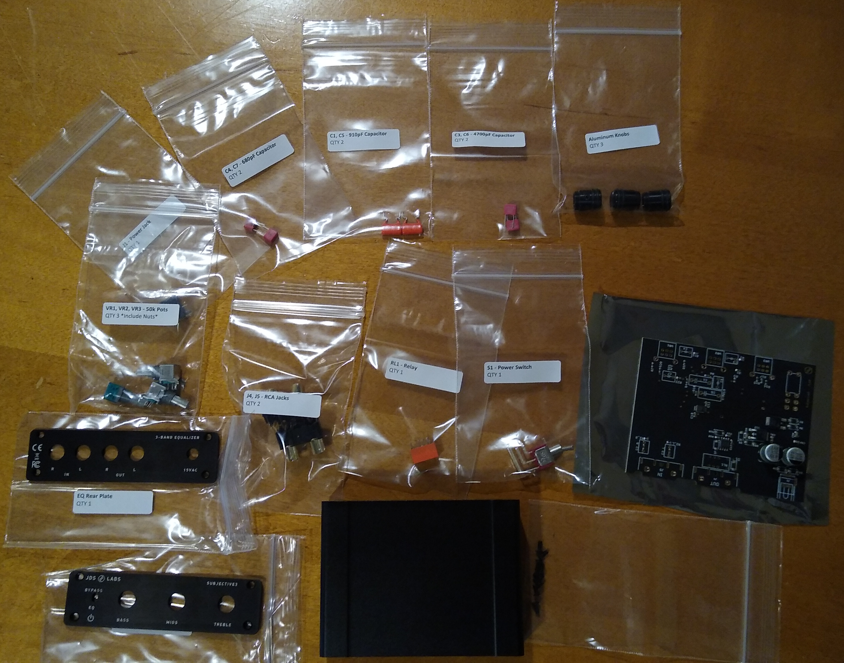 It includes all parts including the power supply (not shown), and the parts are of high quality: Alps RK09 potentiometers, Vishay and WIMA capacitors.
Installing the Parts
Soldering
Assembly is straight-forward. The instructions simply say, “insert all capacitors, solder and trim”. This may sound daunting for noobs, but each part is bagged with a part number that is also printed on the circuit board where it plugs in. Find each number on the board and plug in the corresponding part.
The key here is to use a soldering iron with a very fine tip and relatively low power (12 W). Avoid cold solder joints. That is, heat up the parts to be joined until the solder melts when touching those parts — not the soldering iron tip itself. Use just enough solder to sink and seep through the hole, but not so much that it makes a glob.
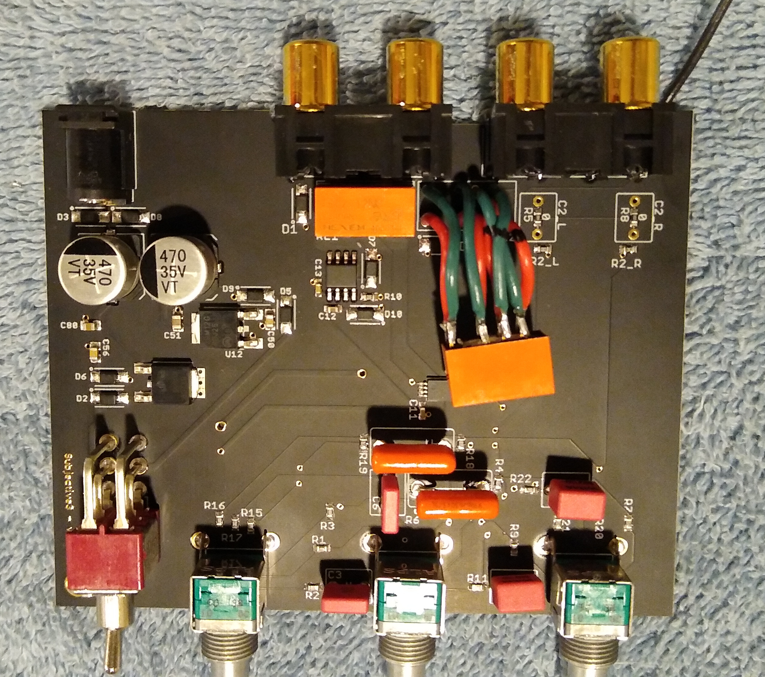
Here’s what it looks like after installing the capacitors and power switch: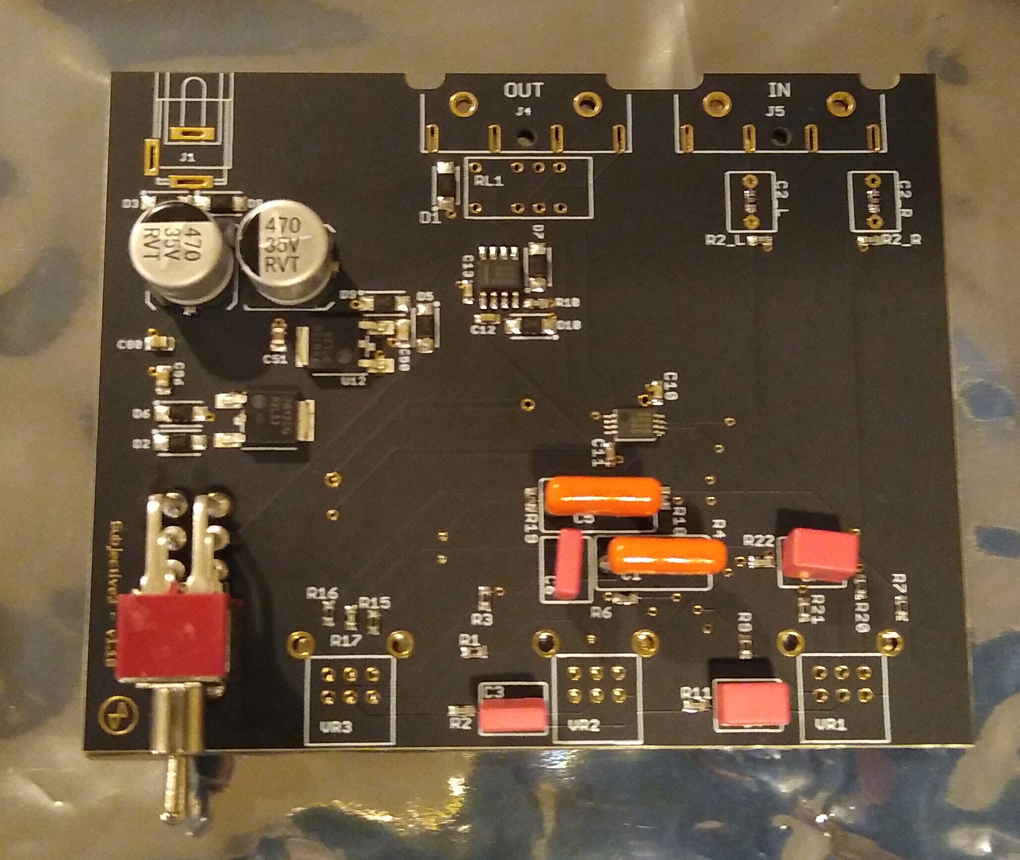
Position and Fit
Some of the parts soldered to the board must match holes in the case when assembled: knobs and switches. If they ride too high or low on the board, the case won’t fit. When I was checking this alignment, I noticed that the case is asymmetric. It looks symmetric at a glance and the asymmetry is subtle, so this would be worth mentioning in the instructions. A picture’s worth 1,000 words, and I reversed the faceplate and case to highlight the difference:
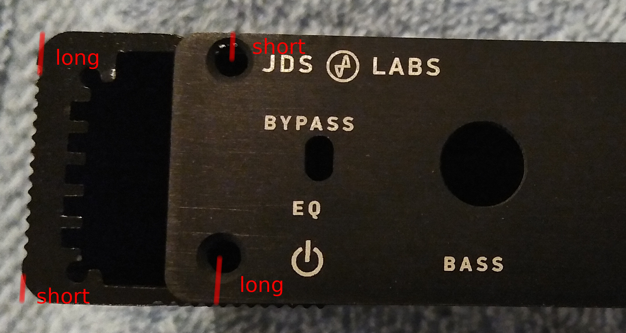 At first, I didn’t notice this and when I checked alignment, it looked like I needed to solder the power switch and potentiometers in a position slightly above resting flat on the board, in order for them to line up with the holes in the case. But it turns out this is not necessary. Solder them flat to the board and use the faceplate as your clue that the “long” distance is the bottom of the case.
Installation: Complete
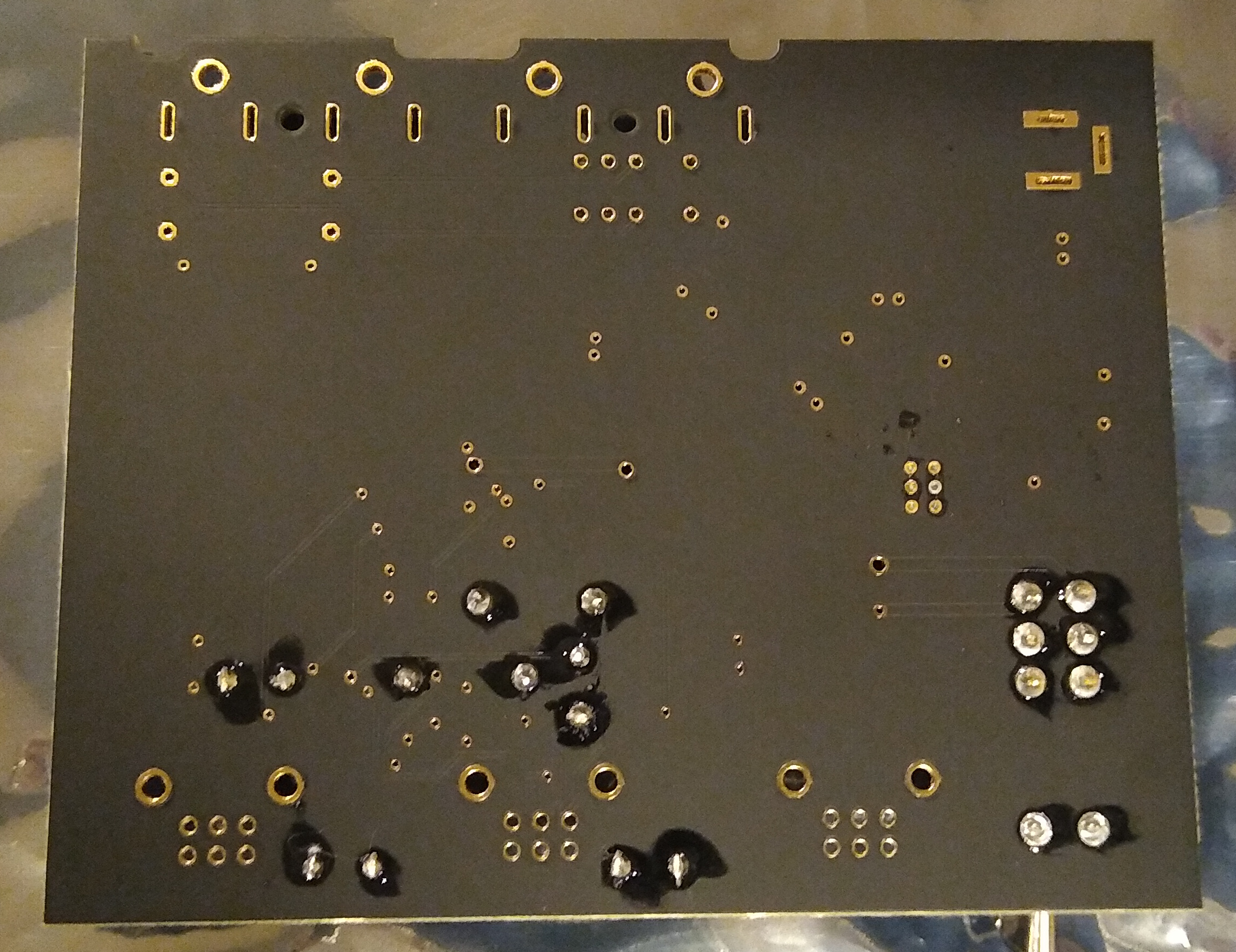
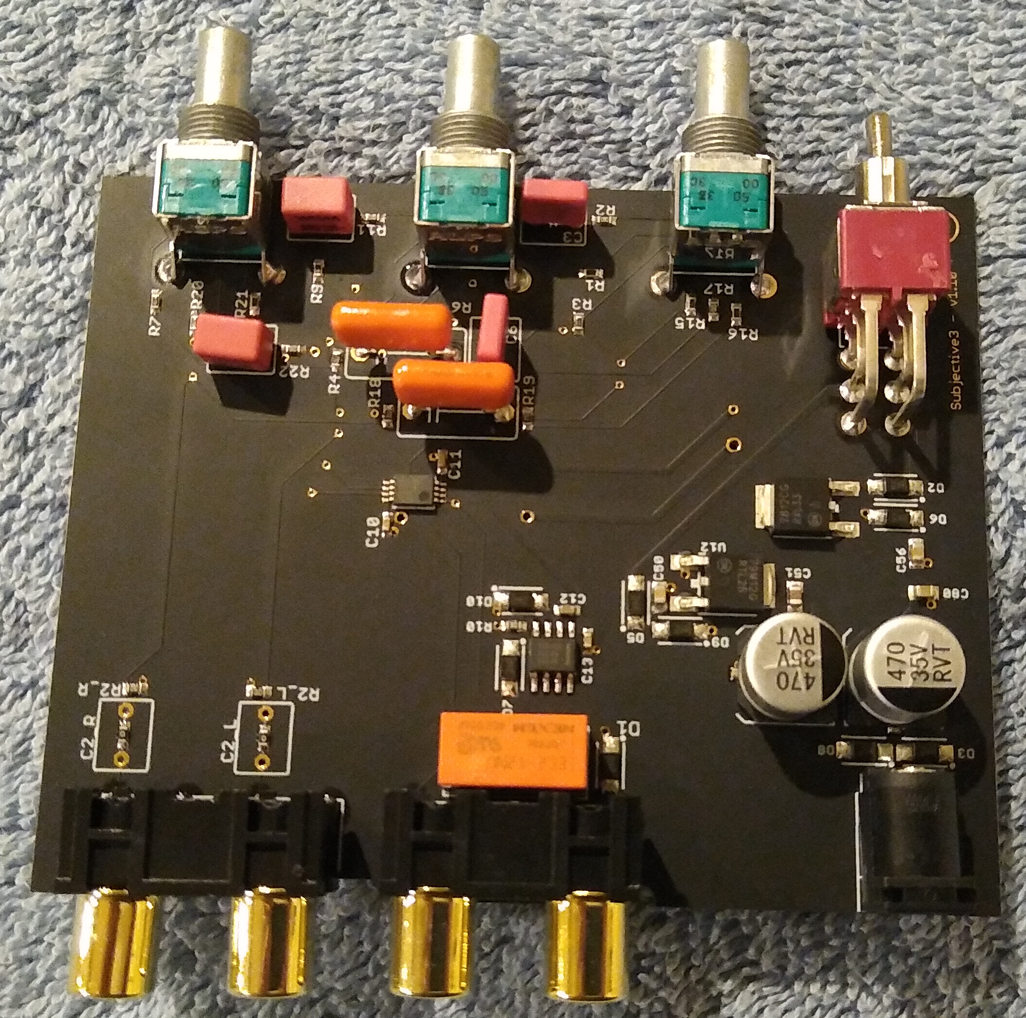
Here’s the board with installation complete: two views of the top and one of the bottom: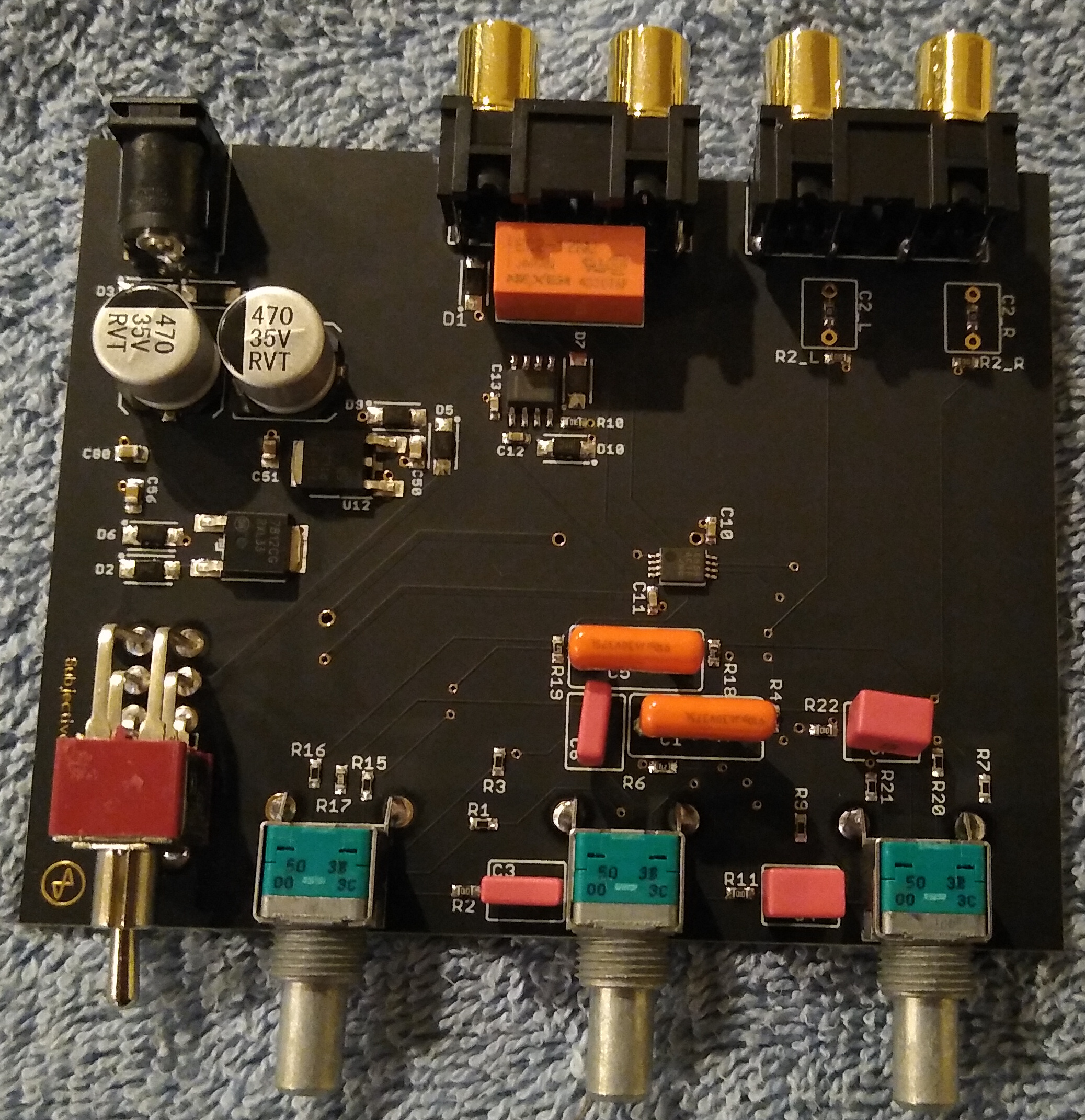
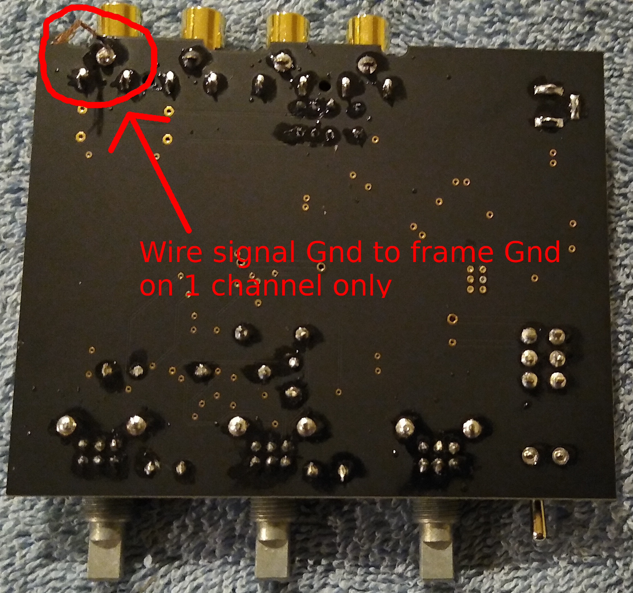 The above photo shows 2 important things: fine soldering, and grounding.
Fine Soldering
Each potentiometer has 8 contacts, 6 of which are in a tight grid. Soldering these can be tricky for those wielding an iron for the first time. Start with the middle contacts and work your way outward. Hold the iron near vertical so it doesn’t accidentally contact other stuff on the board. Be careful to use just enough solder to fill the hole without forming a glob that could touch the nearby pins.
Grounding
In the above left you can see that one (but not both) of the signal grounds is wired to the frame. This is something I discovered years ago through trial & error troubleshooting pesky ground loops when I was building a passive attenuator, and also on a phono head amp that I built. If neither signal ground is connected to frame, you can get a ground loop causing a “hum”. Also, if both are connected to frame. But if only 1 is connected to frame and the other is not, it helps break ground loops.
Assembly: Complete
Here’s what the completed kit looks like up close, with my JDS Atom amp: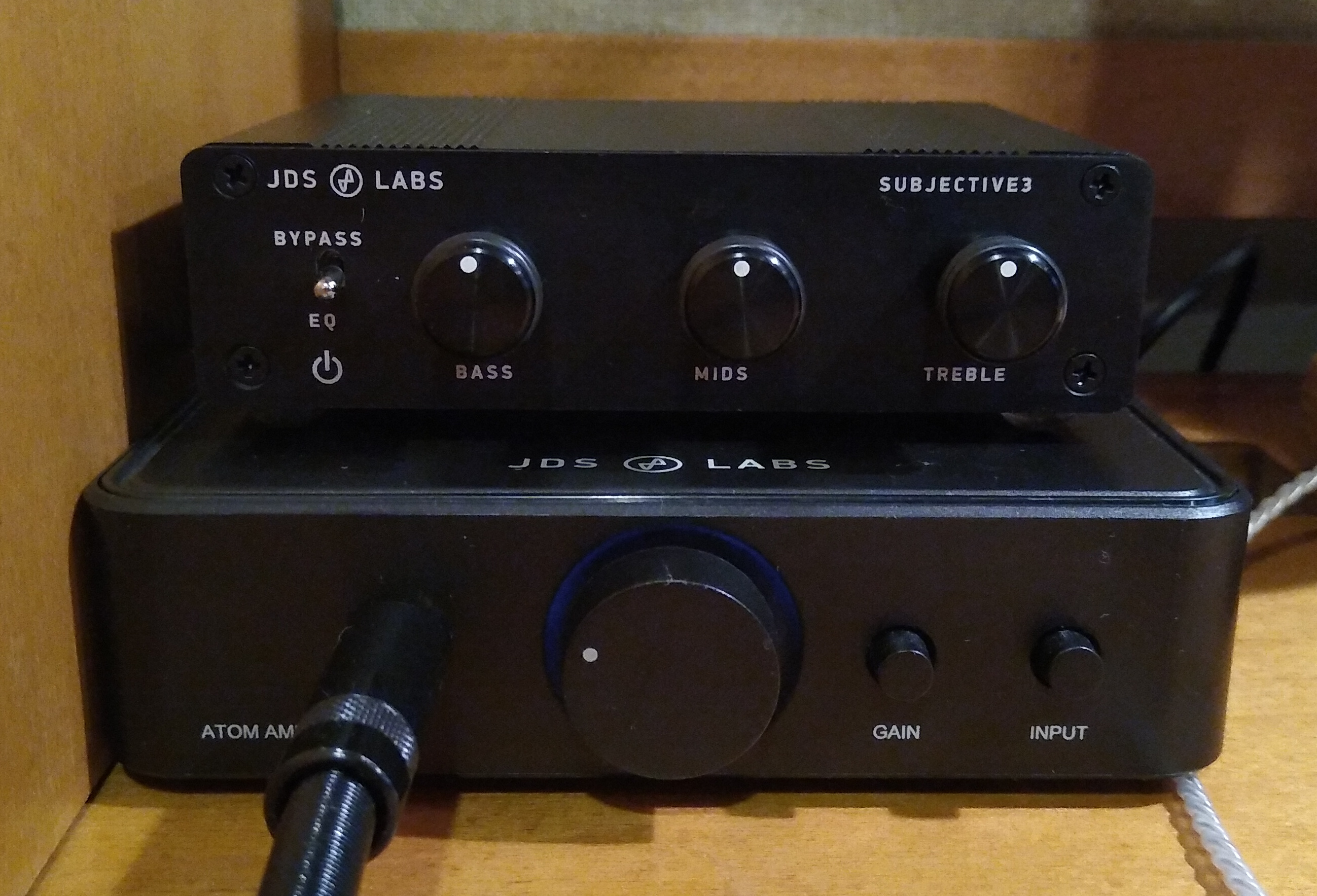 It’s quite small, even smaller than the JDS Atom which itself is a small amp. Here’s what it looks like with the headphones (you can see the wooden headphone stand I made years ago):
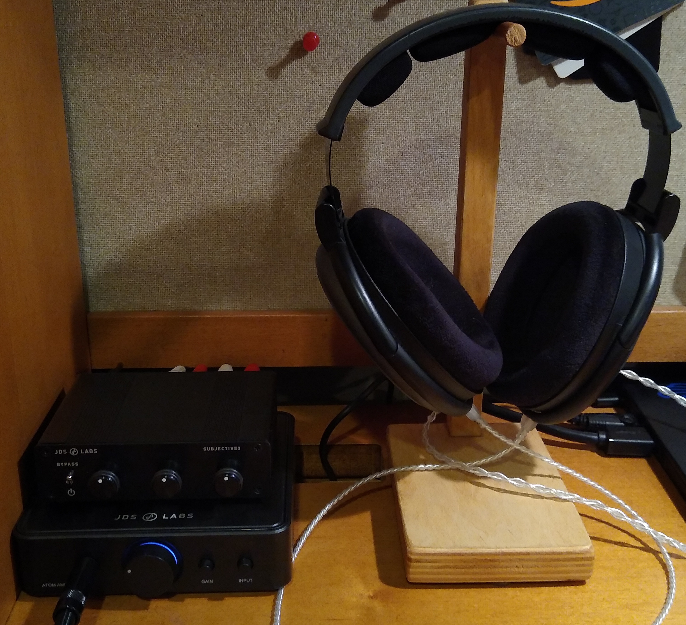
Listening
I powered it up, no smoke — great! I played some music with the tone knobs in the center detent, switching back and forth between “EQ” and “Bypass”. There should be no difference in the sound. Indeed they were almost identical. But there seemed to be a very slight difference. In Bypass mode I heard just a hint of “grain” or “edge”, especially in the upper mids / lower treble where our hearing perception is most sensitive. This was the opposite of my expectation, which was that if there was any difference at all, bypass mode would be more transparent. I was playing a very high quality recording of 5 voice ensemble, which highlights midrange purity, revealing distortion quite well.
Our hearing perception is not reliable enough to trust, but it’s not wrong often enough to ignore. So I put the EQ in a loop with my Juli@ card and used REW to take some measurements. Maybe I’m just hearing things, it’s not really there. Or maybe I made a mistake in the build. Either way, measurements would give a helpful baseline.
Measurements
Baseline
My Juli@ card is the baseline and it is not perfect, so let’s look at its FR and distortion. I played 48 kHz sweeps in REW at digital -1 dB for this: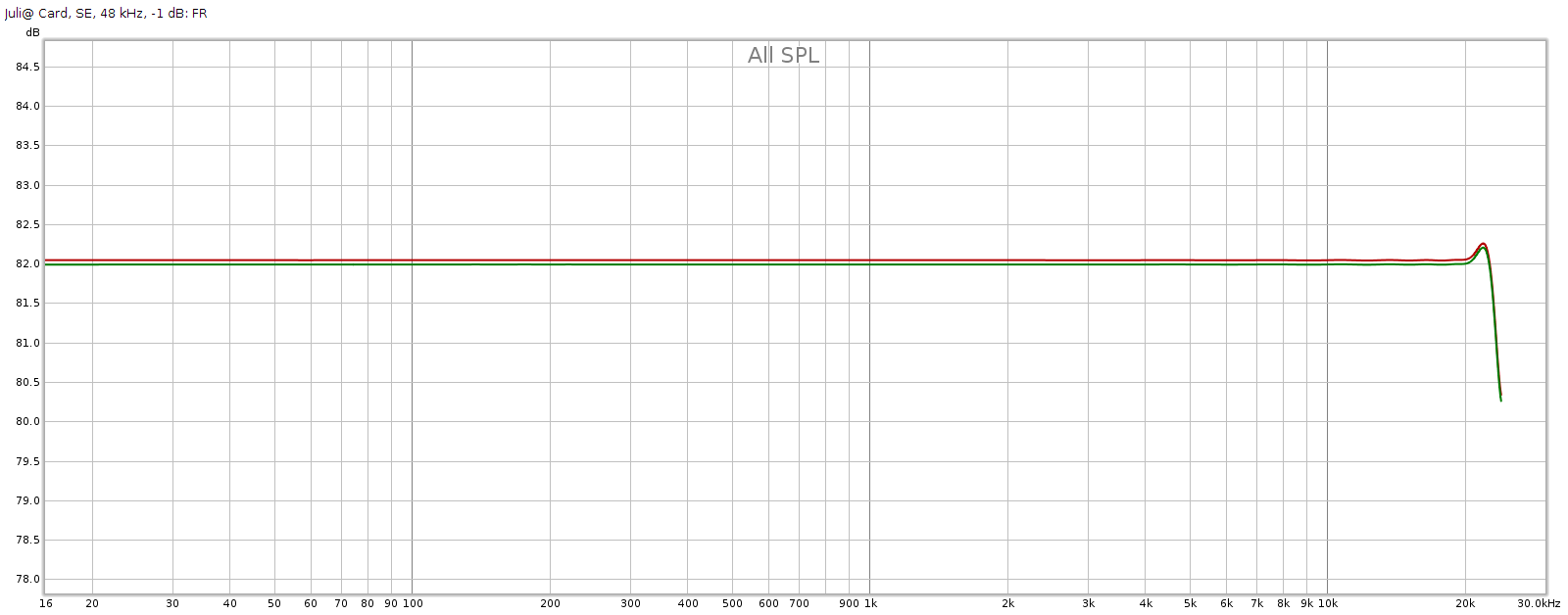
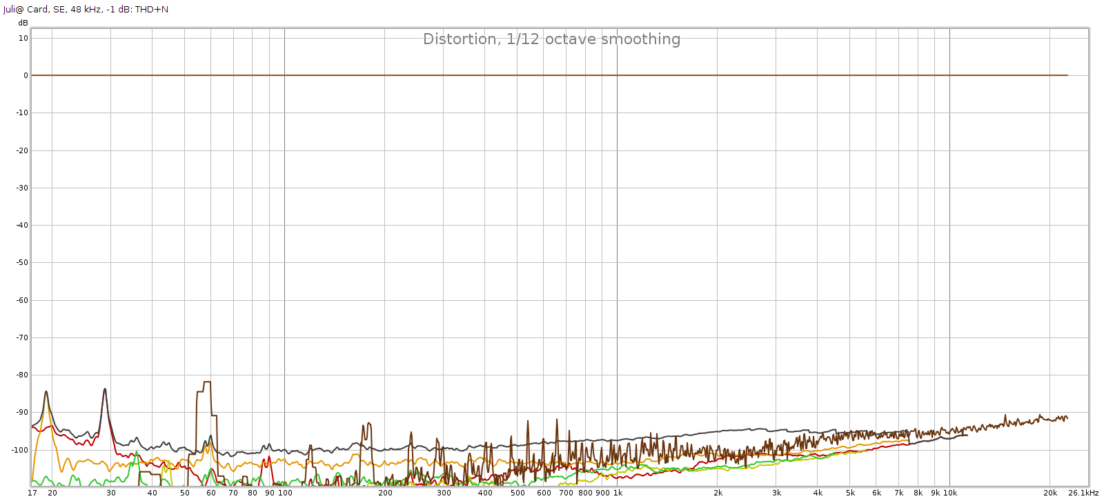 Frequency response is flat with << 0.1 dB variation. The bump above 20 kHz seems to be an REW anomaly. It has a slight channel imbalance which at < 0.05 dB is immaterial. Distortion and noise are mostly -90 to -100 dB, which is the limit for 16-bit.
Subjective 3 EQ: Bypass
Against this baseline, let’s see what the Subjective 3 looks like. First, bypass mode: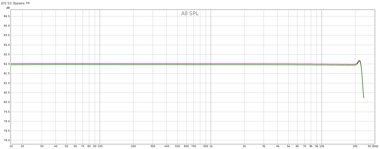
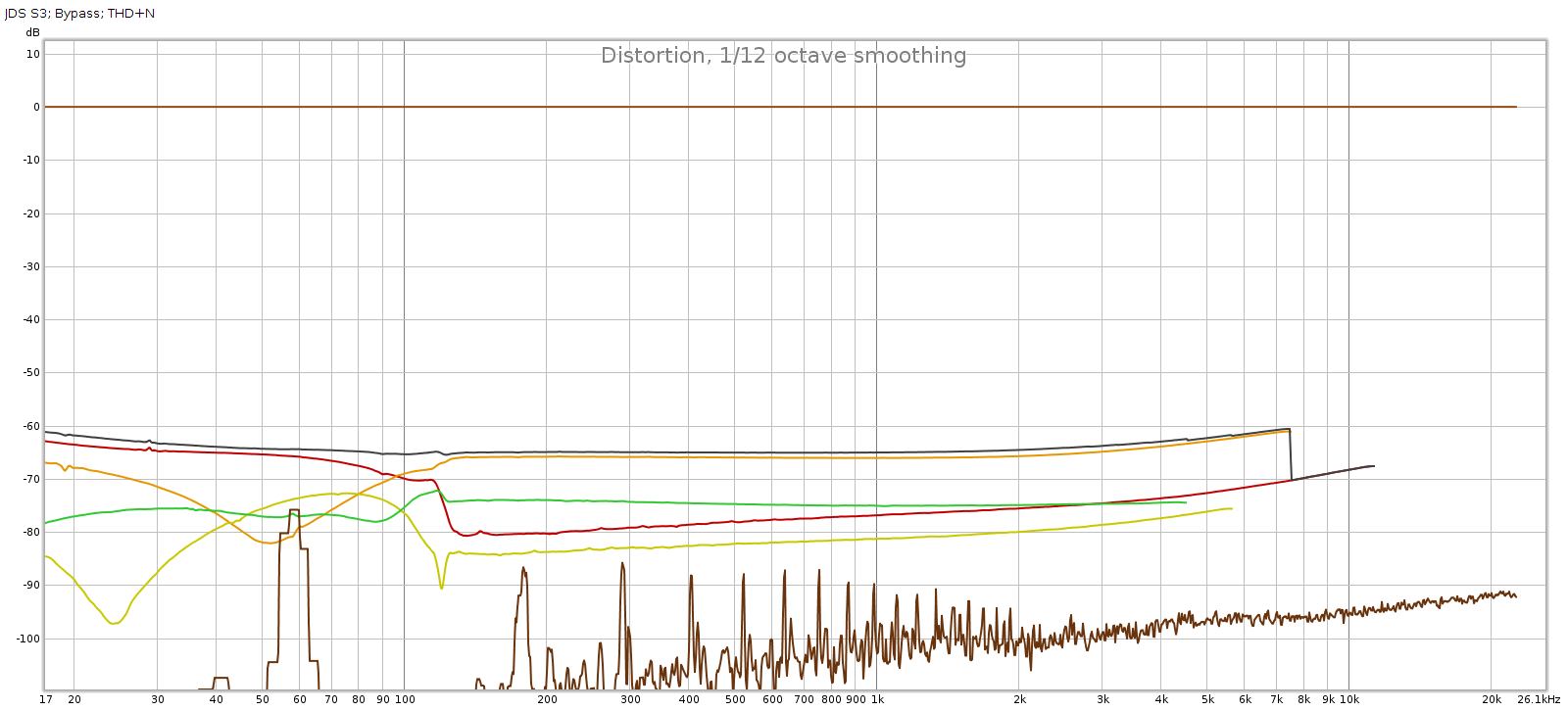 Frequency response is perfect, no difference from the loopback. But we have quite a bit of distortion and noise! At about -60 dB it is likely inaudible, but it is approaching thresholds where it might become audible under ideal worst-case conditions.
Subjective 3 EQ: Frequency Response
Now let’s flip the switch the EQ mode with all the knobs in their center detents.
Here are 3 measurements of the L channel. In between measurements, I rotated each of the tone control knobs several times through its full range then re-centered it to the detent for the measurement. This reveals how consistent it is.
Note: the Y scale is 0.5 dB per division in order to reveal small differences. Red is left, Green is right, just like a boat or airplane.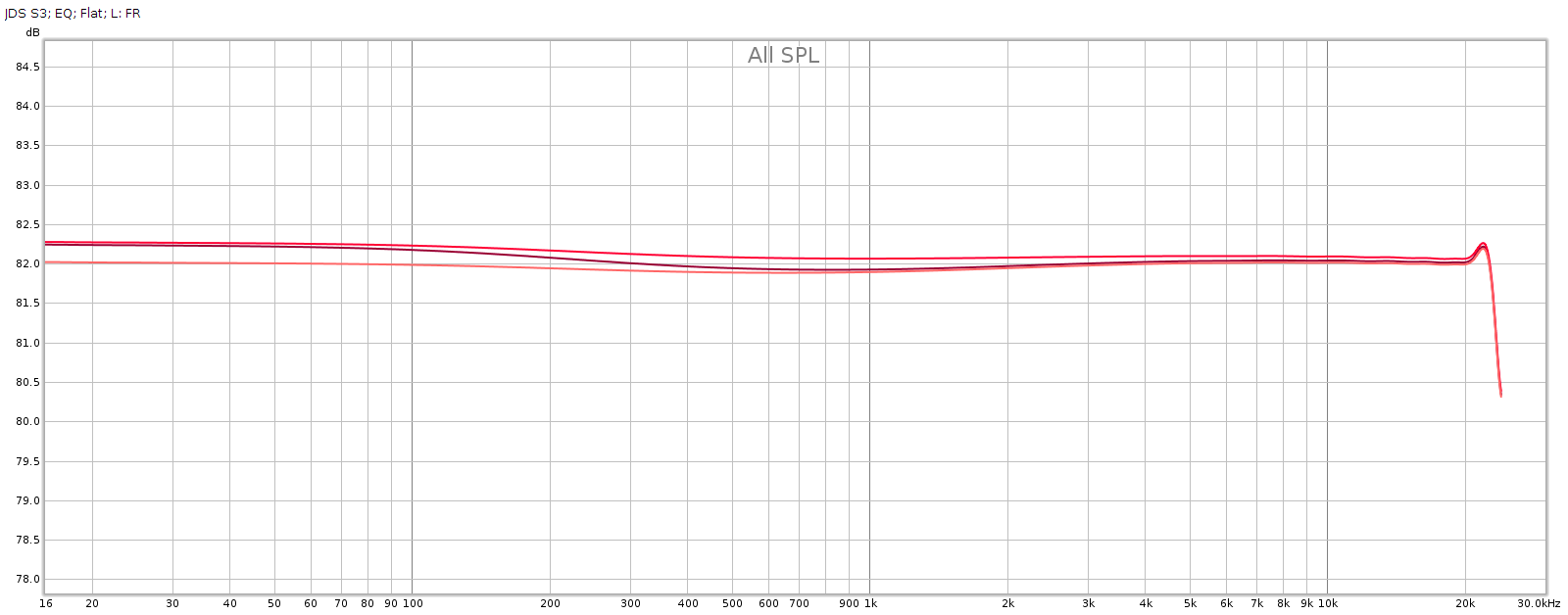 Here are 3 measurements of the R channel, taken the same way:
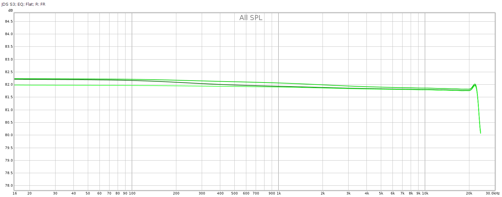 Each shows variations around 0.25 dB. I’m pretty happy with that, it’s about as good as analog potentiometers get. These differences in consistency should be inaudible. Here are the average responses of each, shown together.
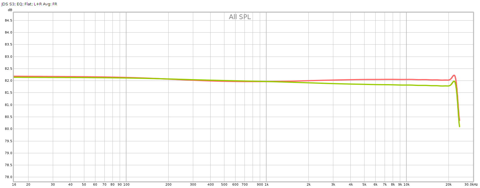 Channel balance is essentially perfect below 2 kHz, at which point it gradually increases to a max of about 0.25 dB at 20 kHz with the L being slightly stronger.
So the consistency of the knobs, and the L-R channel balance, are each within about 0.25 dB.
Subjective 3 EQ: THD+Noise
Now let’s see if that increased noise we measured in bypass mode, is also there with EQ enabled: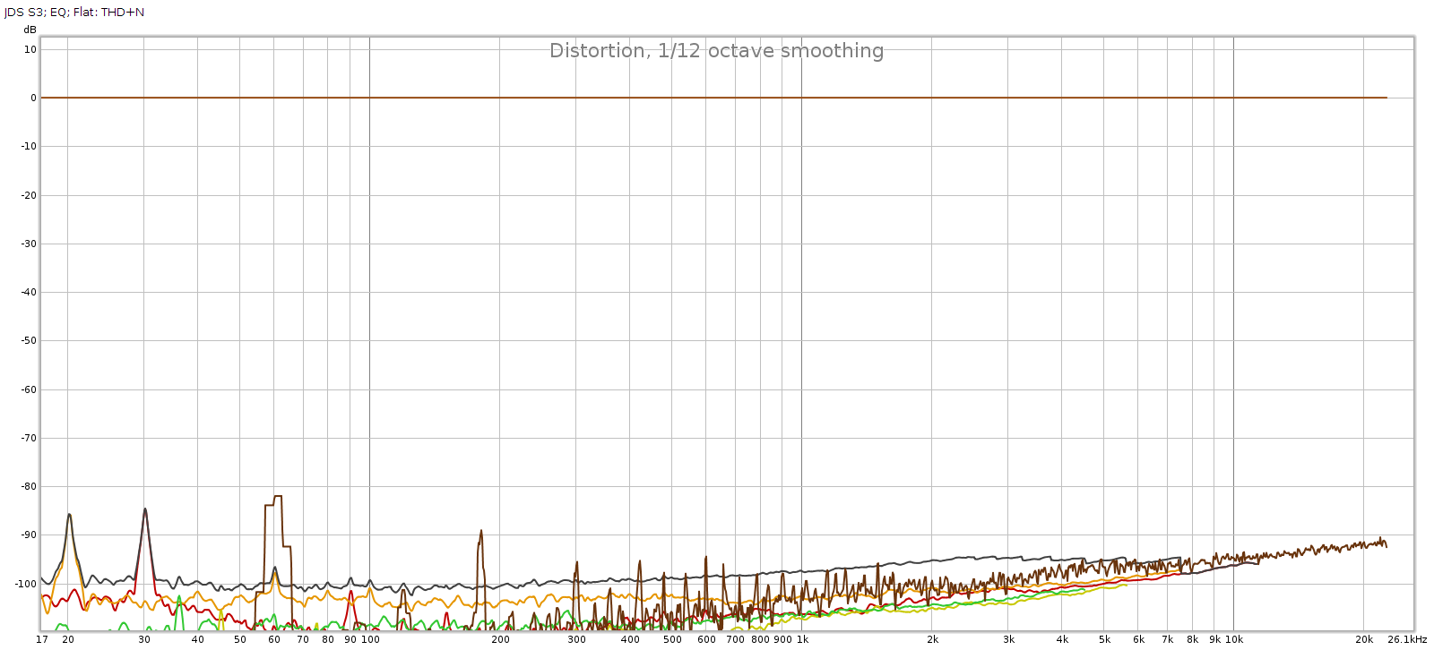 Nope! That’s good news. In EQ mode, it doesn’t add any distortion or noise. Of course, no device is perfect. But whatever it does add is below the levels of my sound card and thus masked and inaudible. JDS Labs publishes a THD+N specification of .0022% which is about -93 dB. We have at least that here.
Subjective 3 EQ: Response Curves
Now let’s see what the tone control knobs actually do to frequency response. I measured each knob at its half-way positions, negative and positive. This is approximate, as I can only eyeball the half-way position. So in the graph below, the curves + and – variations aren’t quite the same, but the important thing is the shape of the curve which shows the frequencies each of the knobs changes:
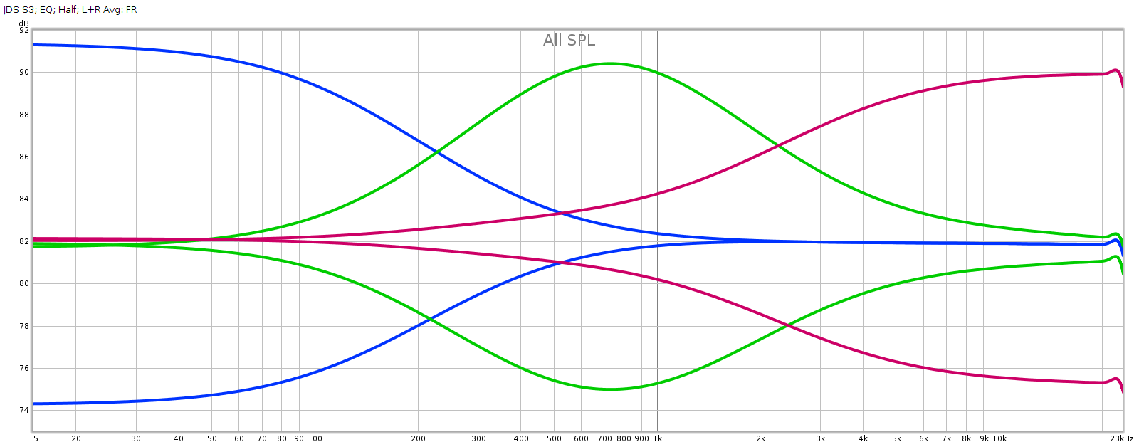
Obviously, blue is bass, green is midrange, and red is treble. And of course I had to zoom out the Y-axis, which is now 2 dB per division in order to keep the curves on-scale. These curves match nicely to the documentation.
Conclusion
The JDS Labs Subjective 3 EQ is a nice little kit. It is inexpensive, uses high quality parts and is easy to build with clear instructions. It sounds and measures clean and transparent in EQ mode. It has good consistency and channel balance. The knobs have a lot of range; just turning from 12:00 (center detent) only “1 hour” to 11:00 or 1:00 makes a noticeable difference. This makes the knobs quite sensitive and the full range is far more than I’ll ever use.
The only real drawback is that bypass mode introduces a fair bit of distortion. At -60 dB it’s close to thresholds of inaudibility, but may become perceptible on certain kinds of well engineered recordings on very high quality playback gear. That said, this issue is unique to bypass mode; the S3 EQ is consistent and clean enough to simply leave powered on in EQ mode all the time.
Note: I contacted JDS Labs in case the distortion in bypass mode was due to a mistake I made in building or measuring this device. They confirmed that it is known, and they’re revising the board to fix this. As I write this update it is Feb 2022 and they just sent me the revised board and parts so I can build another one. I’ll report back soon…
The problem is fixed. The S3 in standby mode now measures the same as a loopback connector, as it should. No more added distortion. In active mode (turned on) it is the same as before. JDS will be shipping this revised version soon.
Here’s the new board. I couldn’t simply solder the 2nd relay into the board, because 2 pairs of pins had to be reversed. So I wired it individually in order to cross pins 4-5 and 8-9. That was tricky for someone with only moderate soldering skills like myself. In production boards, this relay can be soldered directly into the board just like the one next to it, much easier.