All posts by Mike Clements

Slide Rules!

Background

I learned to use slide rules in high school in the 1980s. My physics teacher was one of the most memorable teachers in my life, “Mr. Jordan”. He said that slide rules can be faster than a calculator, and they promote a better understanding of numbers, orders of magnitude, and significant figures. They are not as accurate as calculators, but real-world problems only need 2-3 significant figures. As such, anyone who used a slide rule instead of a calculator would get a bonus 10% on every test, and answers would be considered correct if they were within 1% of correct. I was one of the few who took him up on this offer.

He handed out small circular slide rules, saying they were easier to use than linear slide rules (which is true, since circular never goes off scale). I don’t remember exactly what model slide rule it was, but the closest I know of today is the Concise model 28N. It was either that, or something very similar.

Note: I now have a Concise model 300, which is their biggest and best. The C and D scales are 8 cm in diameter, which is a circumference of 8π which is 25.2 cm, or about 10″. This is the slide used used in the photos below.

All we needed for physics was multiplication and division, and squares & cubes. Jordan would throw problems like, “A Porsche 944 goes 0-60 in 8 seconds. If it weighs 3000 lbs. with fuel and driver, and half the engine power goes toward acceleration, how much power does the engine produce?”

Since then I’ve been a slide rule fan. I use one when flying for computing fuel burn rates, density altitude, altimeter & airspeed corrections. I also keep one around for doing random calculations that come up during the course of a day. When 2-3 sig figs of accuracy is sufficient, it’s quicker & easier than a calculator.

Slide rules are antiquated tech. So why learn to use them? It’s for these secondary benefits mentioned above. And they are fun.

Introduction

Slide rules are based on the concept of a logarithm (aka log). Every log has a base, and the log is what power you raise that base to get some other number N. Examples:

  • Log base 10 of 100 is 2, because you raise 10 to the power 2 to get 100, or 10^2 = 100
  • Log base 2 of 32 is 5, since 2^5 = 32
  • Log base 10 of 42 is 1.623 (approximately), or 10^1.623 = 42

The reason logs are useful, and how they led to the invention of slide rules, is because exponents are additive. That is: 10^5 = 10^(2+3) = 10^2 * 10^3

That means if I know the logs of 2 numbers A and B, call them La and Lb, then La + Lb is the log of the product A*B.

Note: Computer scientists take advantage of this when multiplying many tiny numbers together. Since computer floating points have finite precision, multiplying many tiny numbers leads to underflow. Instead, take each number's log and add them all up. Then at the end take the inverse log of that sum. This gives you the same product with much higher precision since it never underflows.

Now suppose I have 2 rulers with markings from 1 to 10. But instead of being spaced linear like a normal ruler, they are spaced logarithmically. If I line up 1 on the first ruler, with some number A on the second ruler, then the mark for some other number B on the first ruler will line up with the value of A*B on the second ruler.

A picture’s worth 1000 words, so here’s a circular slide rule.

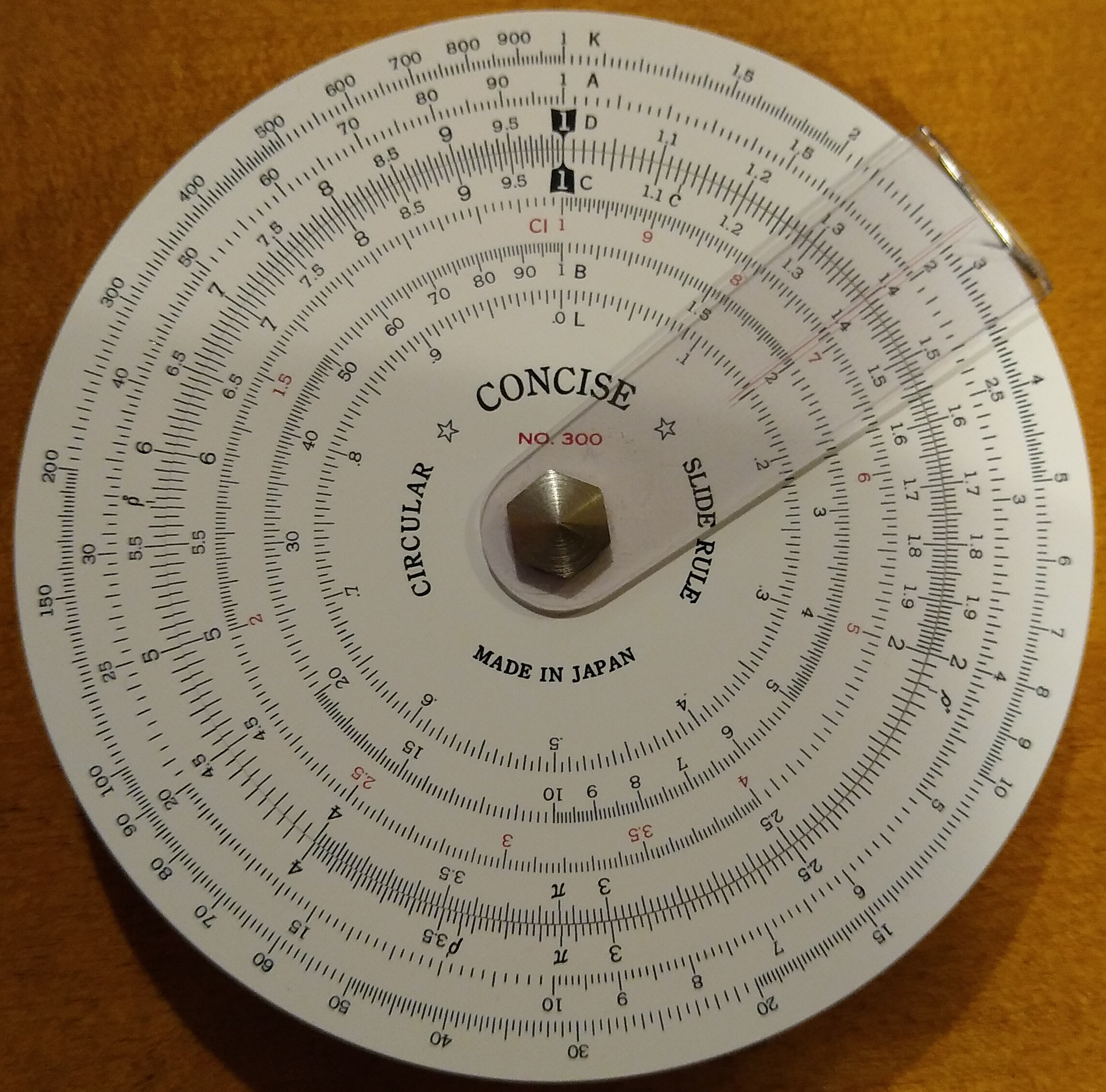
The clear marker with the thin red line is called the cursor. We’ll ignore that for now. See how the two black highlighted “1” values are aligned? Each of those scales (inner and outer) are logarithmic. That’s why the range from 1-2 takes about 1/3 of the scale while the range at the upper end is much more compressed. As you start from 1 and go up the scale, the numbers start out spread apart and get more squished together.

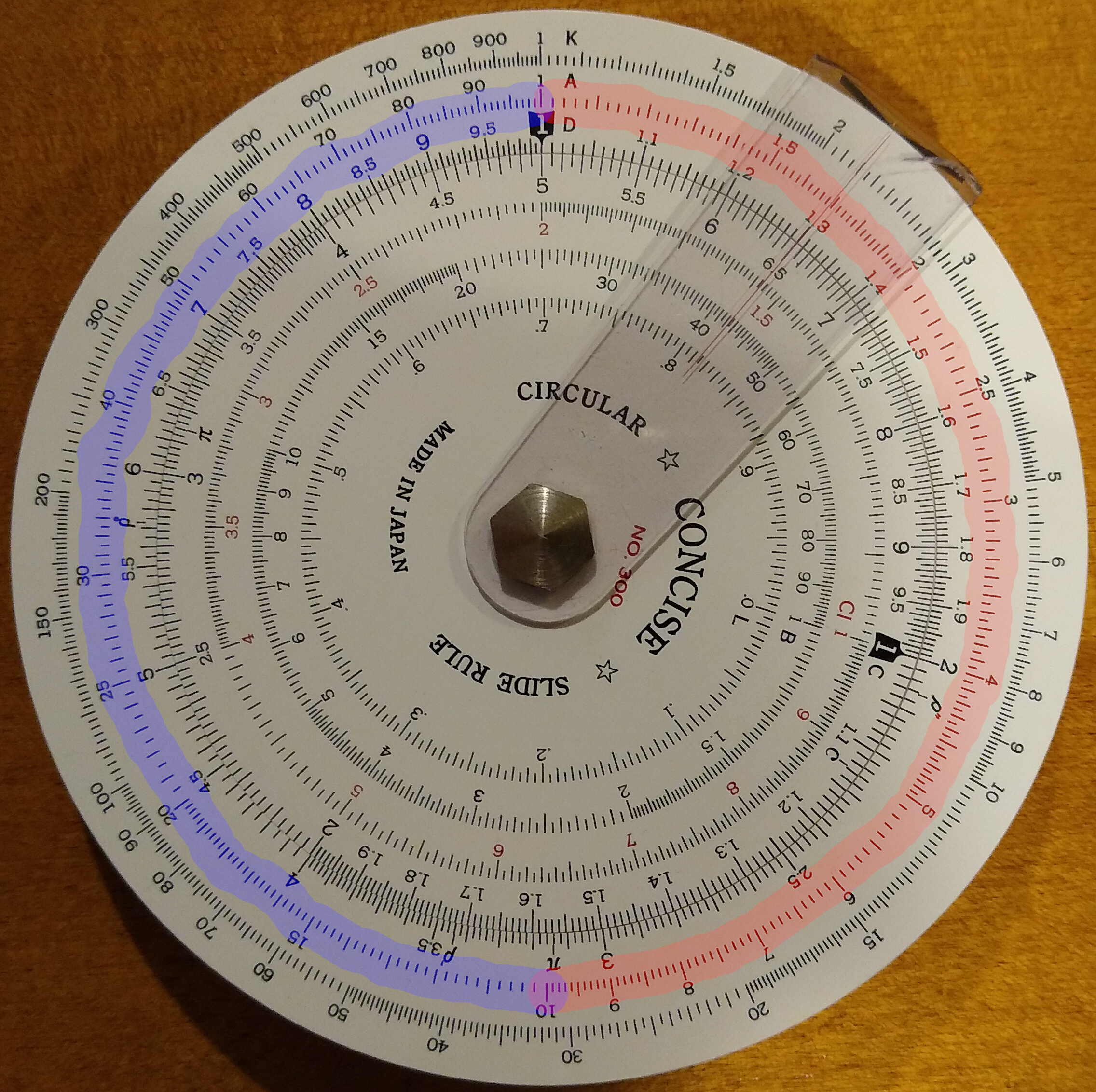
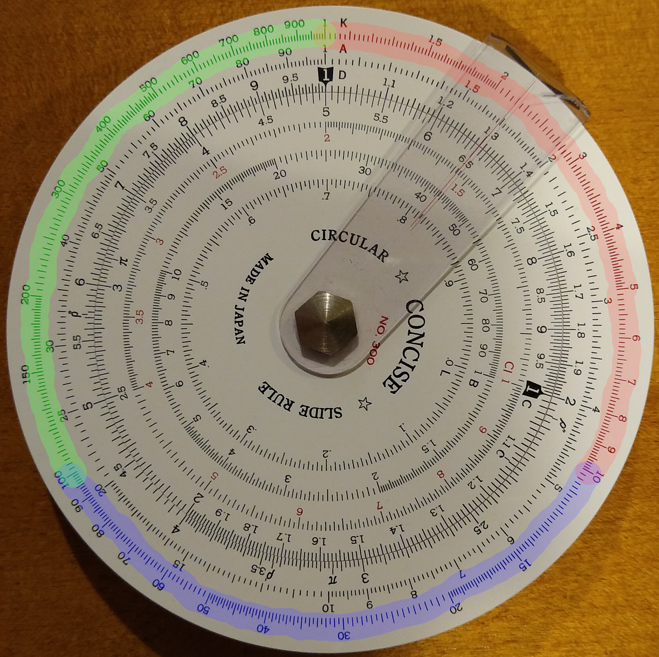
Watch what happens when we slide the inner “1” to line up with the outer “2”:

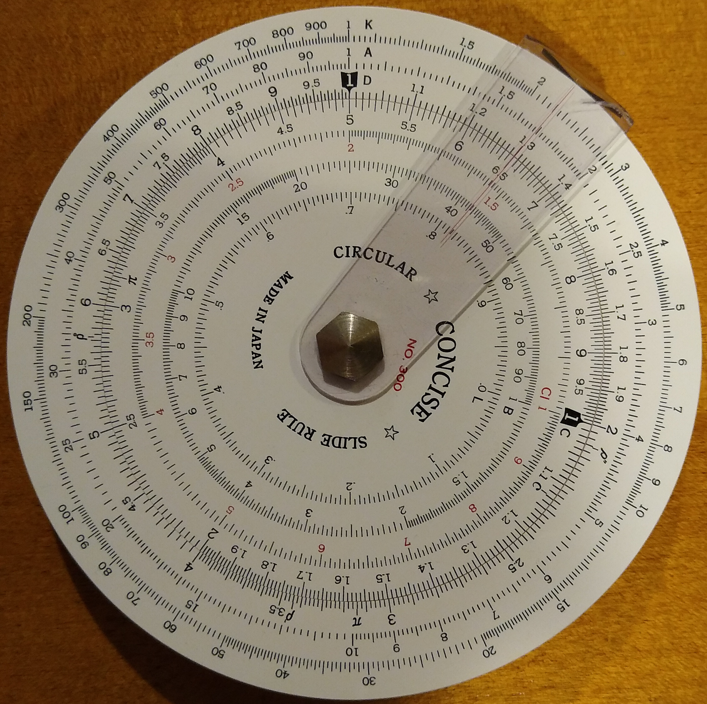
If this were a linear ruler, it would be shifted by 1 over the entire scale: 1 to 2, 2 to 3, 3 to 4, etc. But not here, where 1 matches 2, 2 matches 4, 3 matches 6, 4 matches 8, etc. Every number on the inner scale matches the number exactly twice as much on the outer scale. And every number on the outer scale matches the number exactly half as much on the inner scale.

Below I’ve highlighted what I’m talking about. Each number on the inner scale matches to exactly twice its value on the outer scale.

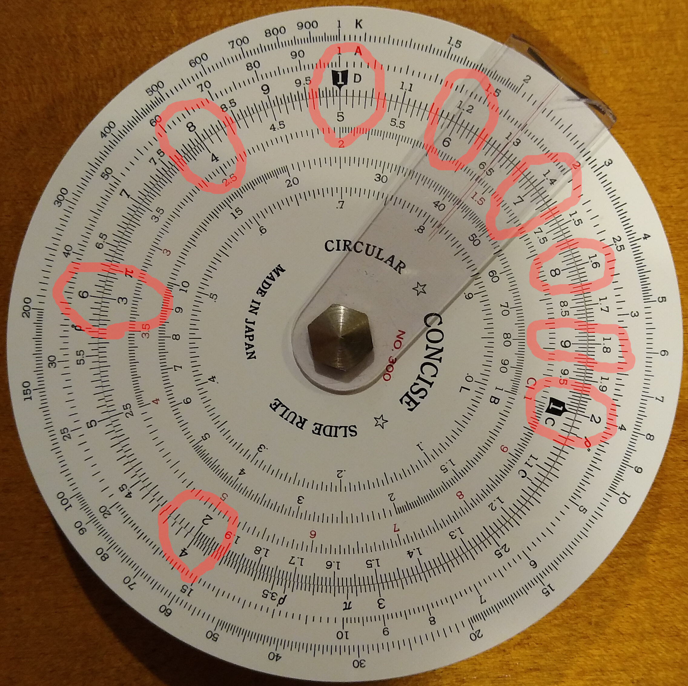
In short, this slide rule is set up to multiply or divide any number by 2.

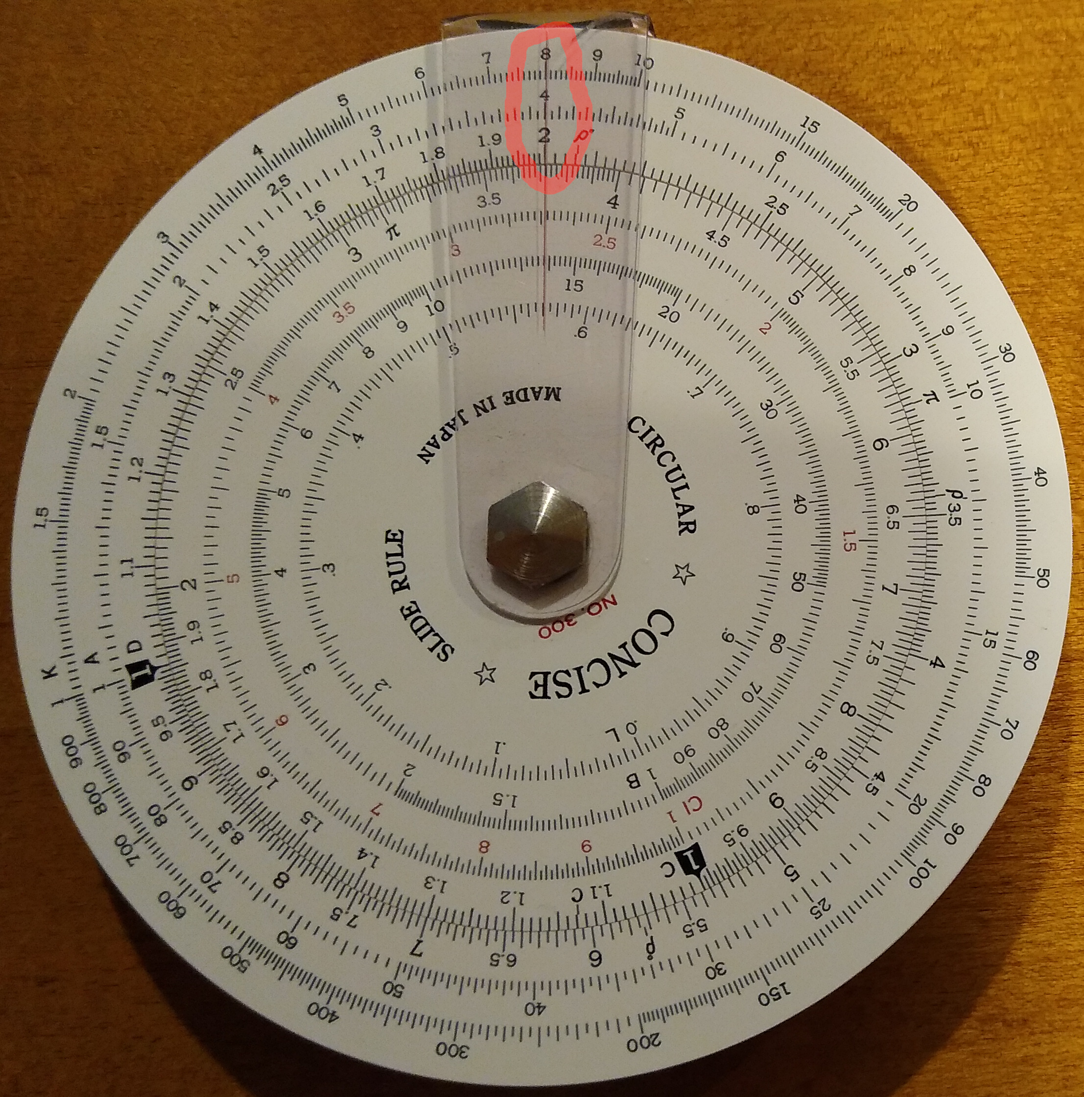
Yet here’s the kicker: this is not specific to the value 2. It’s downright magical. Here’s the slide rule with 1 matched to 3:

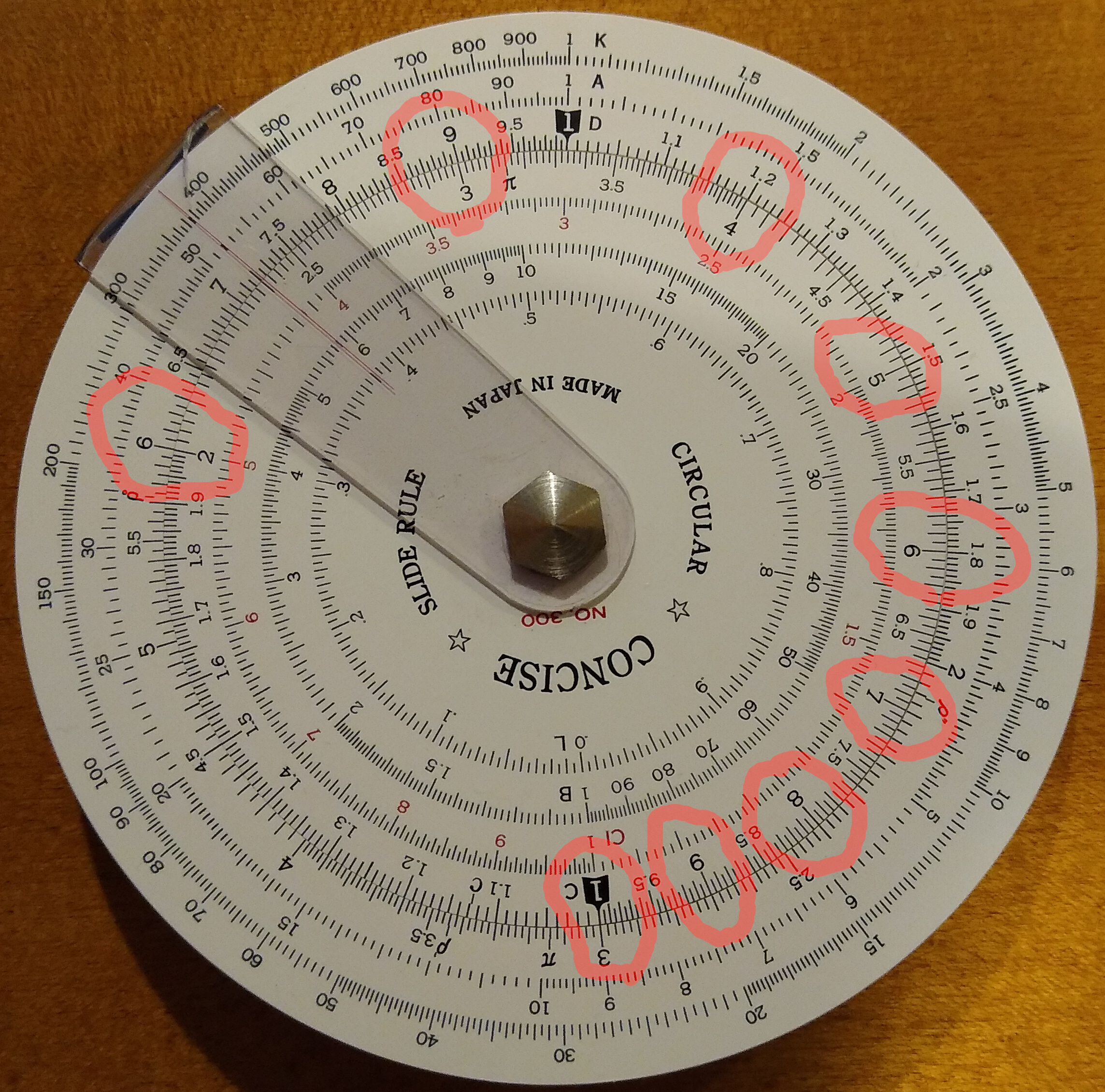
Similar scenario, only now we can multiply or divide any number by 3. And look below for 4:

Of course, this doesn’t just work for integers. You can do this for any number in the scale. In fact, now you know how to multiply or divide using a slide rule.

BTW, these are called the C and D scales. On this slide rule, D is the outer and C is the inner. That’s what the C and D are in photos.

What about Zeros and Decimals?

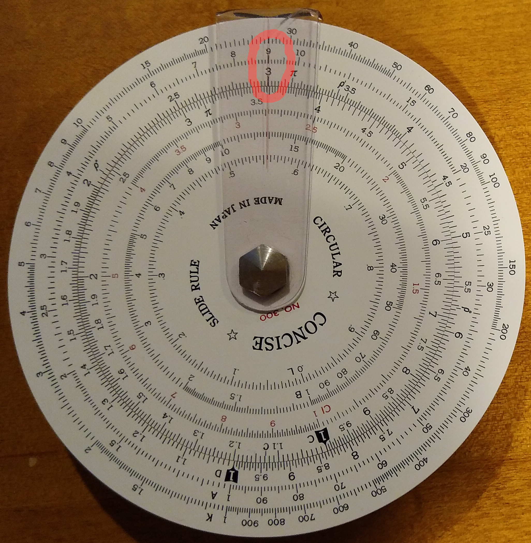
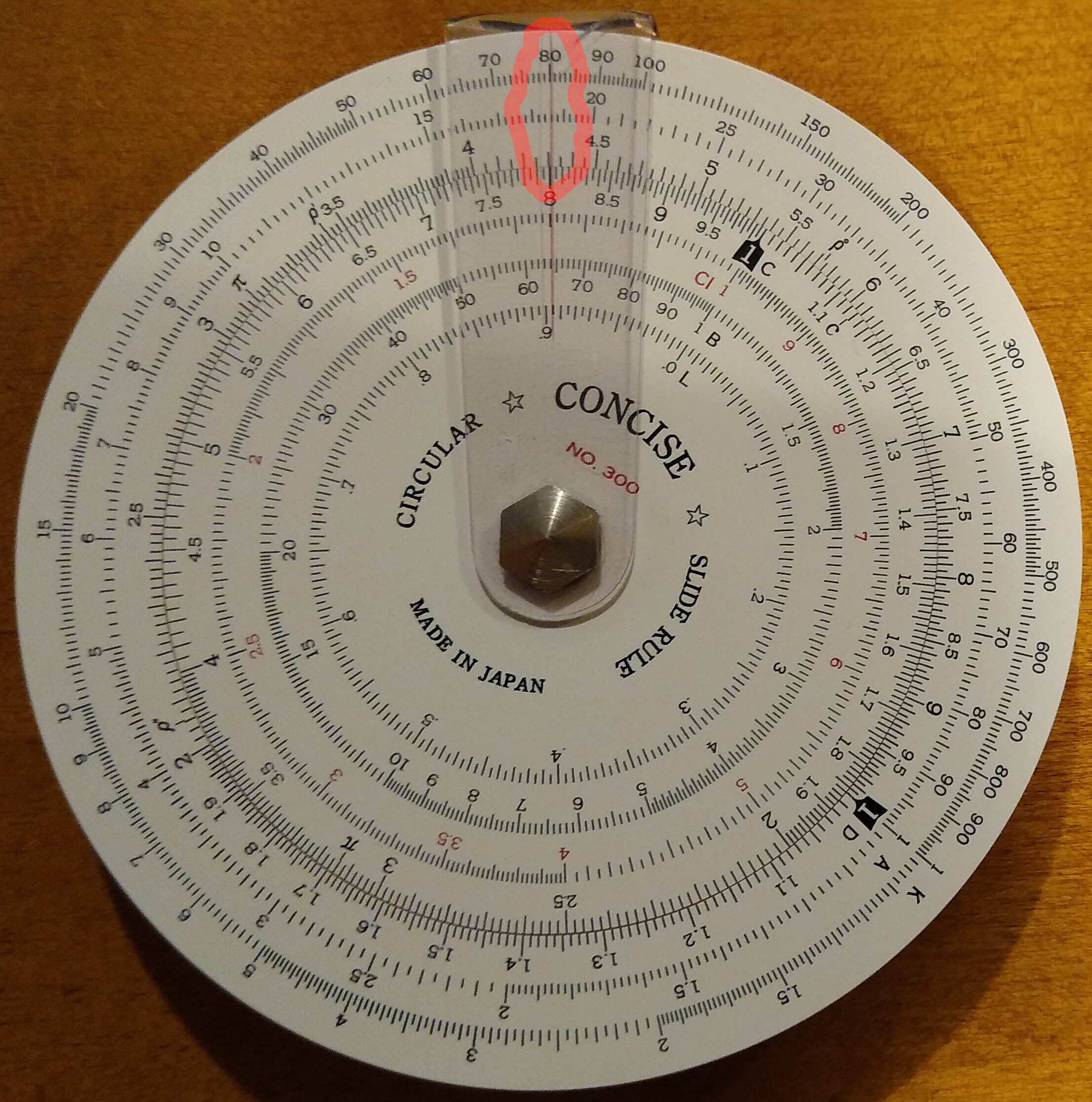
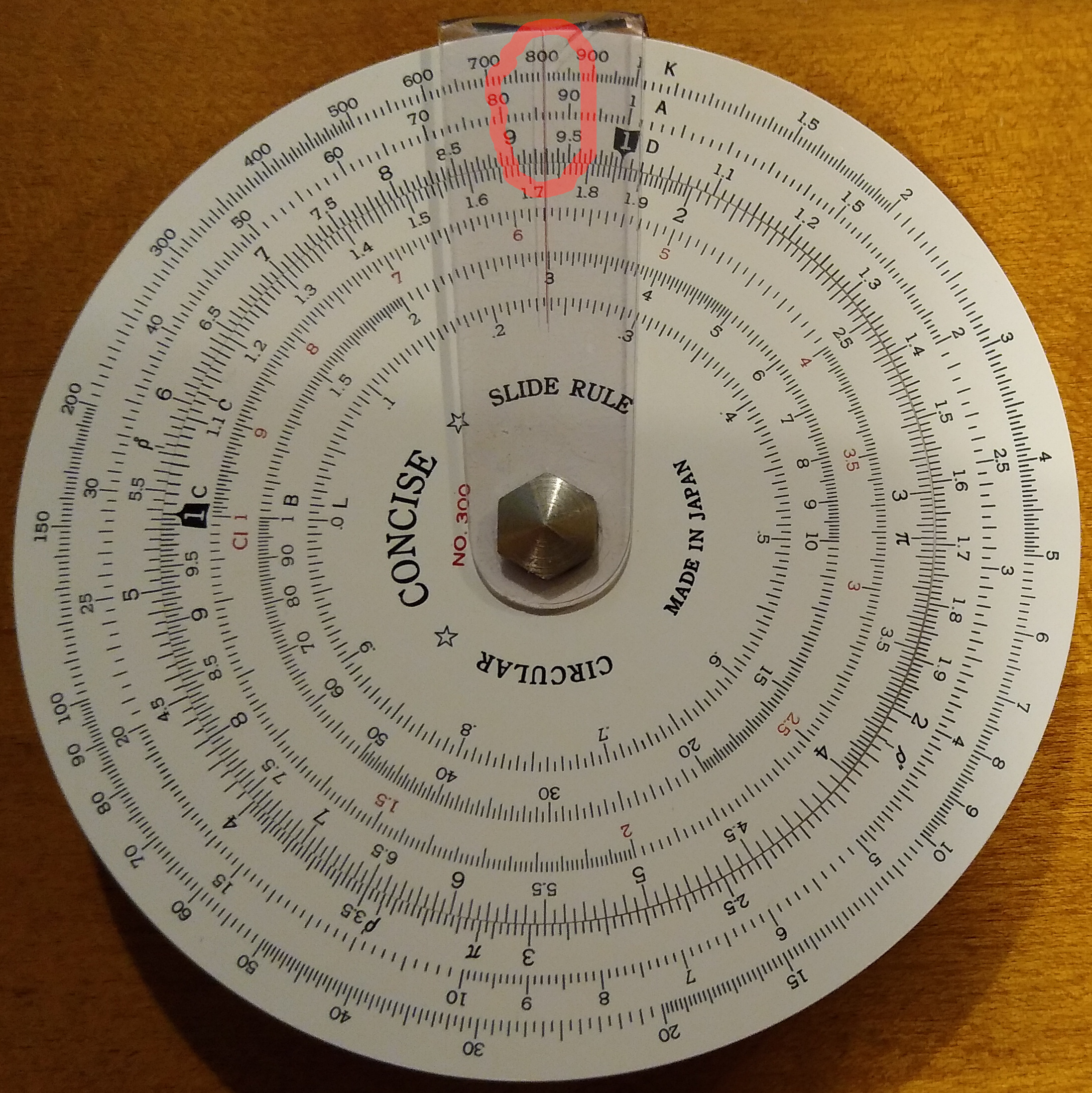
Suppose you want to multiply 3*4. First line up the C scale 1 with the D scale 3, then look at the C scale 4, which points to the D scale 12. See the picture below:

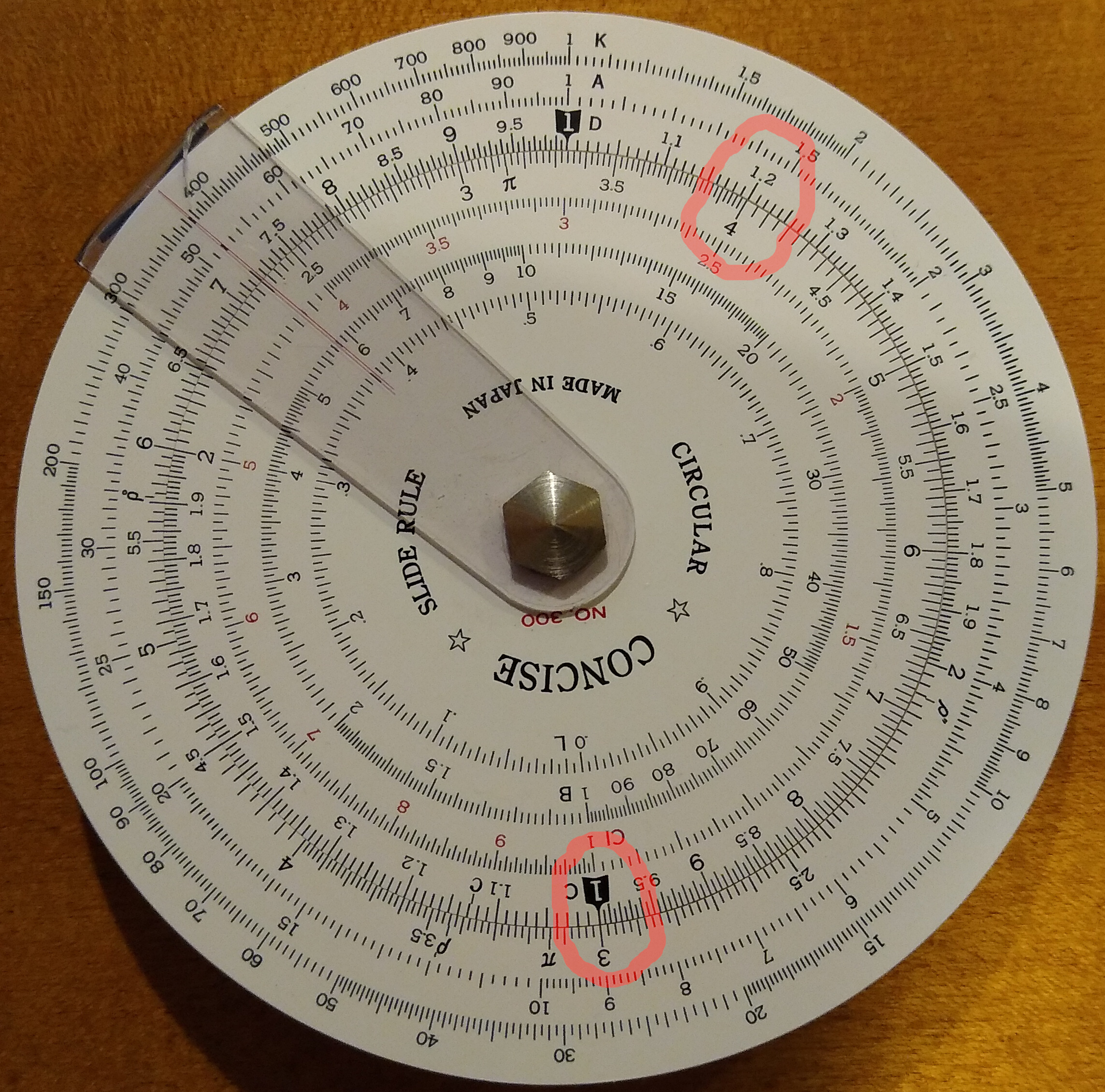
You might notice that it doesn’t actually say 12, it says 1.2. We happen to know that 3*4 is 12, so we interpret the 1.2 as 12. When you use a slide rule you need to keep track of the decimal point.

This is where circular slide rules are easier to use than straight ones. On a straight rule, this 3*4 problem is greater than 1, so it goes off scale and you can't read the answer. You need to shift to additional scales CF or DF (C folded and D folded) to read the results. Circular slide rules never go off scale, they just wrap around. Much simpler and easier!

All Those Scales!

So far we’ve only covered the C and D scales. You can see that slide rules have several other scales. Most slide rules have these scales:

  • C & D: multiplication & division
  • CI: inverses
  • A & B: squares & square roots

Some slide rules also have these scales:

  • K: cubes & cube roots
  • S, T, ST: sine & tangent

Let’s go through these one at a time.

CI Scale: Inverses

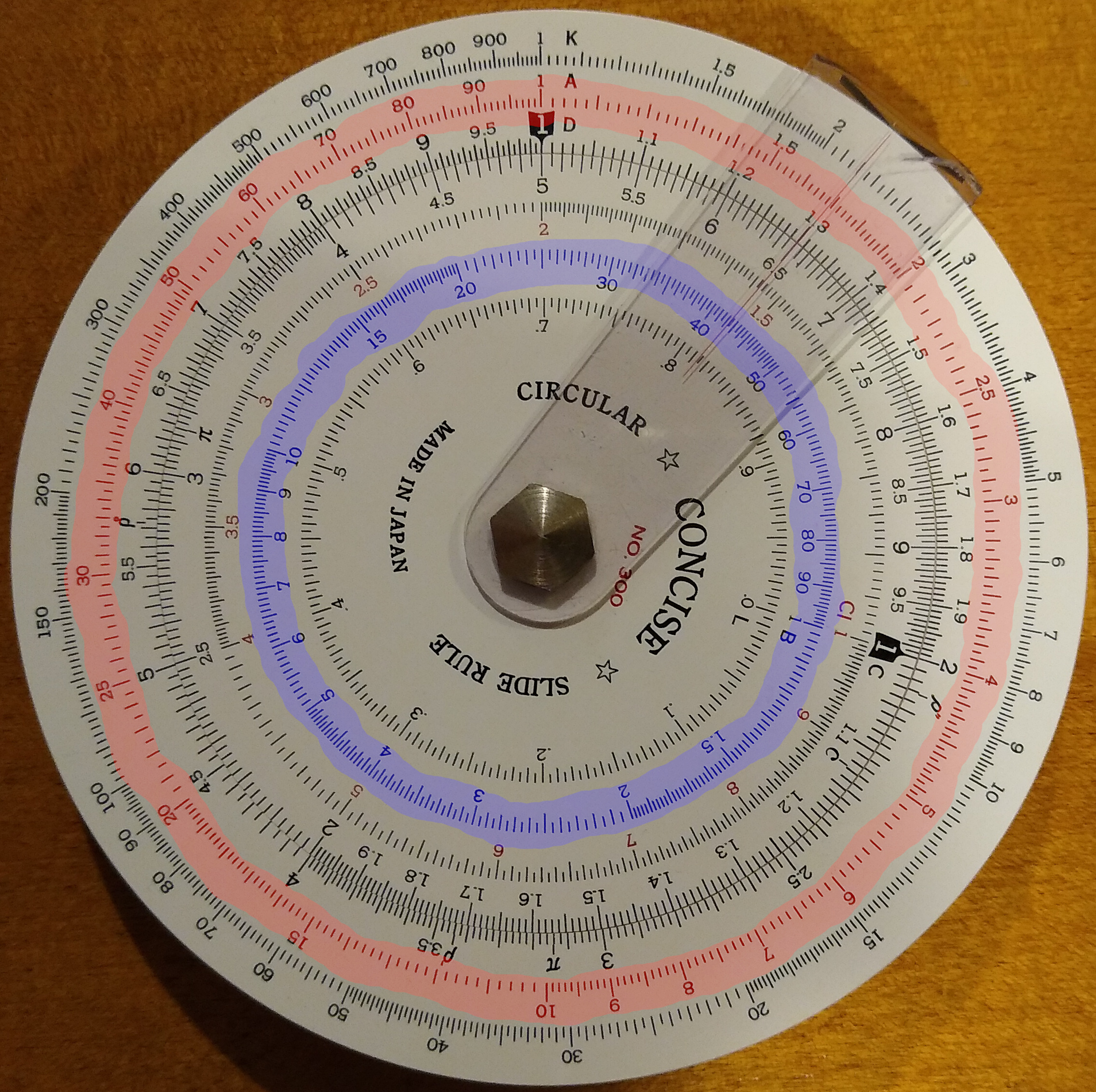
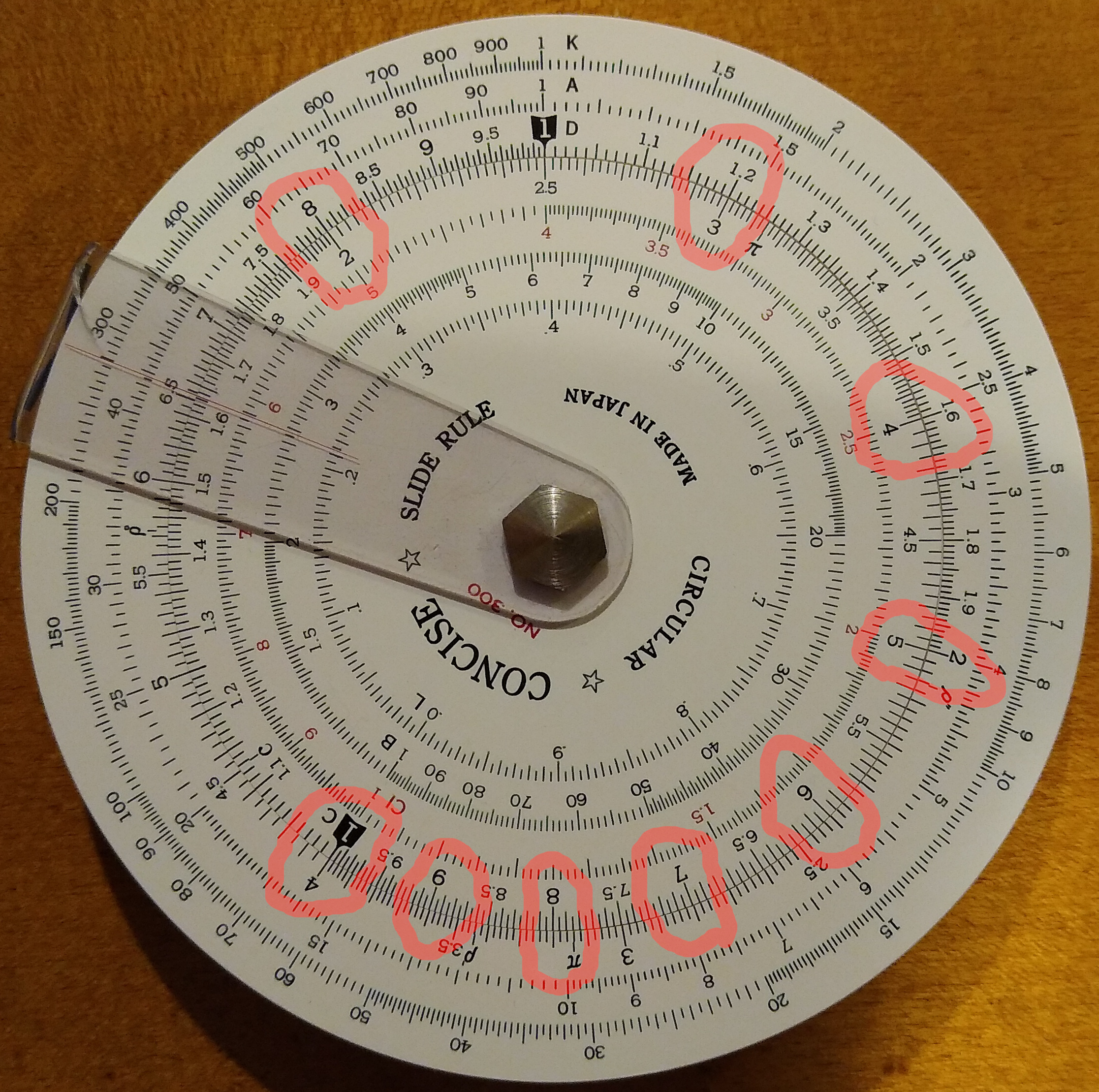
The CI scale is the inverse of the C scale and it’s marked in red. Simply put, it is the same scale but going backward – in the opposite direction. The C scale increases clockwise; the CI scale increases counter-clockwise. Each number on the C scale, lines up with its inverse on the CI scale. For example, 2 lines up with 5 since the inverse of 2 is 0.5.

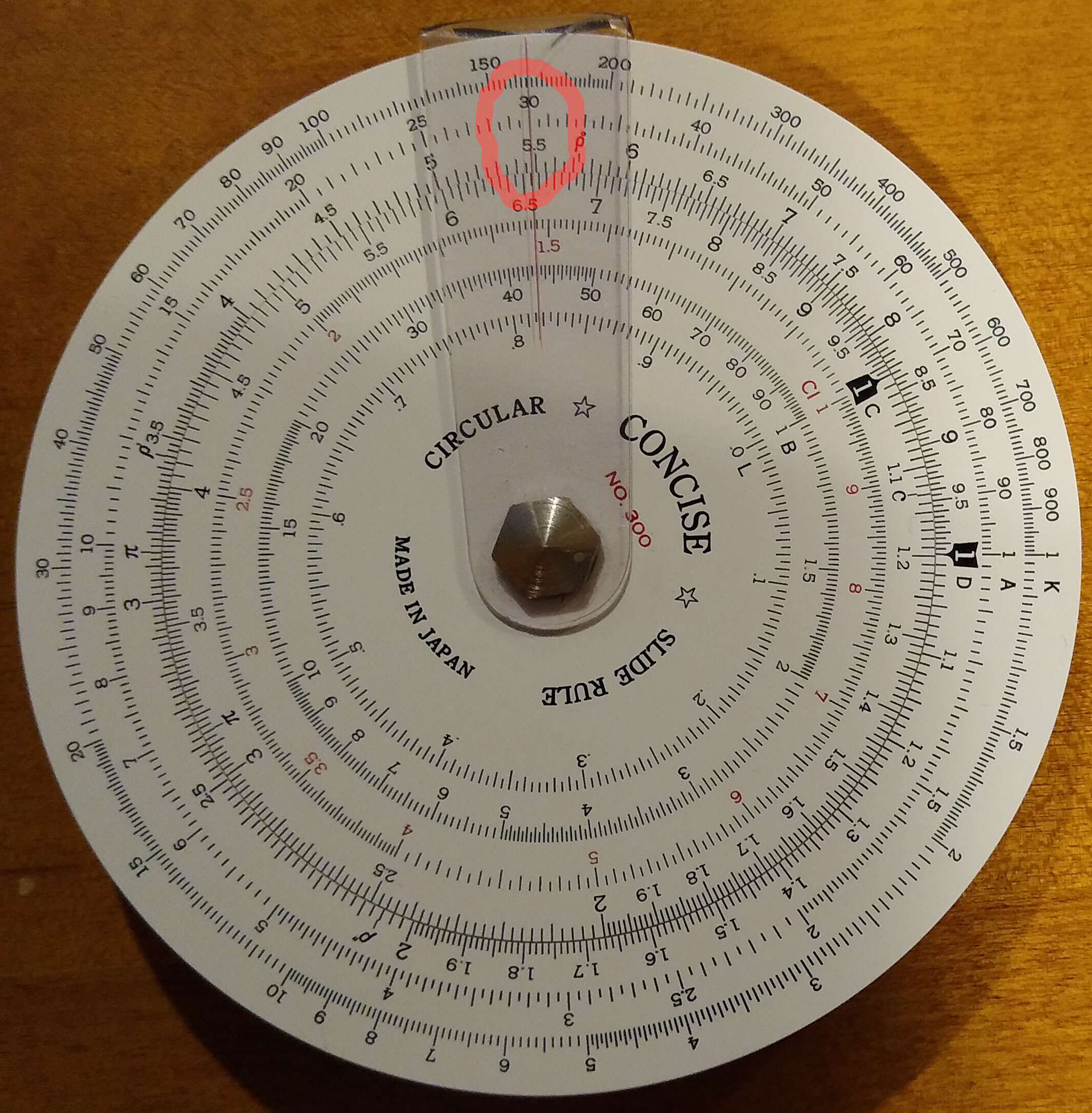
Here, the cursor comes in handy to read these scales. For example, below the cursor is lined up on 4, so you can precisely read its inverse on the CI scale, which is 0.25. But as you can see all around the dial, each number on C always lines up with its inverse on CI, and both scales increase in opposite directions around the circle. I’ve marked some obvious points, like 4 and .25, 5 and .2, and their inverses.

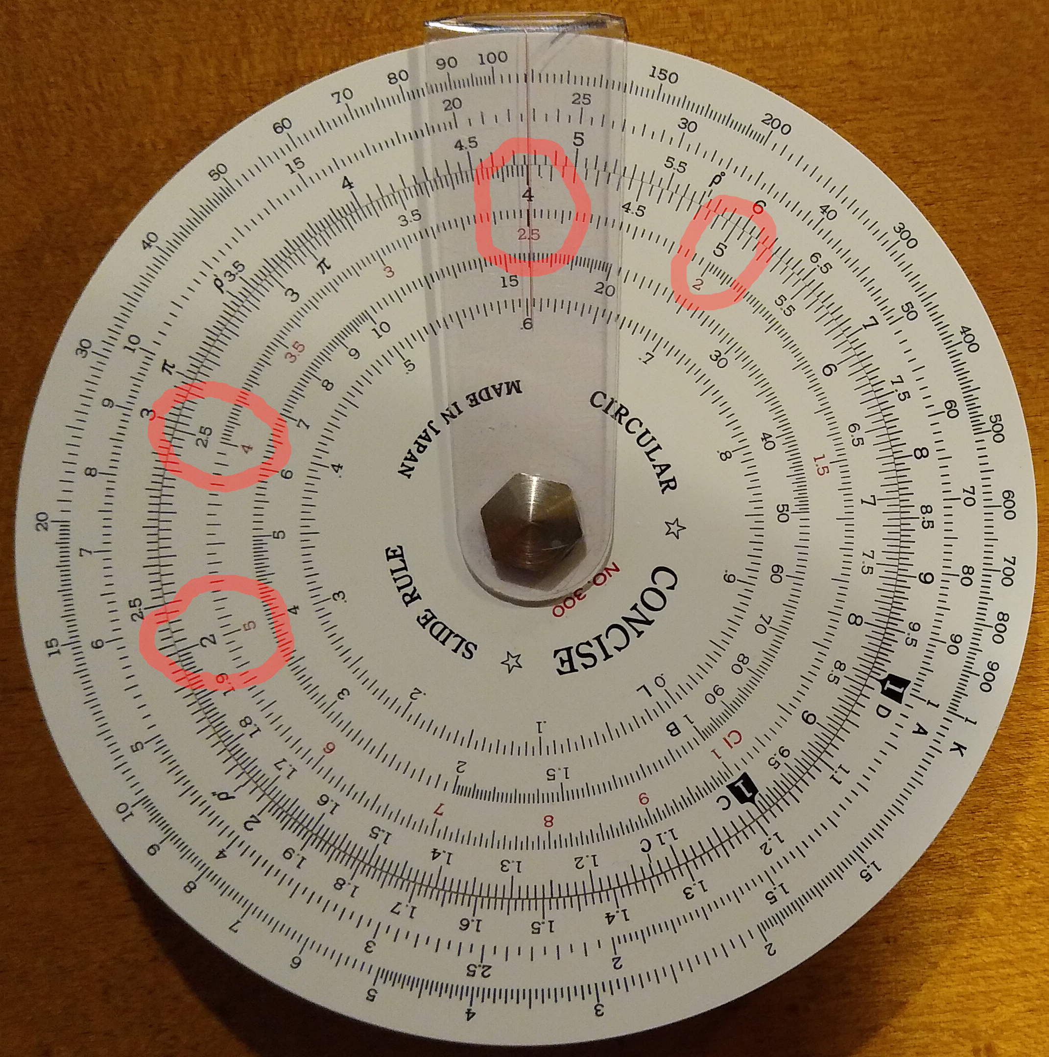
For example, reading for yourself you can see that 1/7 is about 1.43. My calculator says it’s 1.42857. So we got 3 significant figures of accuracy there (more on sig figs later).

Conclusion

Now that you can use a slide rule for basic computations, have some fun practicing. I cover some of the other scales in part 2.

Slide Rules: Past the Basics

For background, here is part 1. It introduces slide rules and covers basic usage with C, D and CI scales. Here we cover the A, B and K scales for squares, square roots, cubes and cube roots.

A Scale: Squares and Square Roots

The A scale shows the square of each number on the D scale. Conversely, the D scale shows the square root of each number on the A scale.

Below the cursor shows that 3 on the D scale matches 9 on the A scale.

Note that as the D scale goes from 1 to 10, the A scale goes from 1 to 100. This means every single-digit number in the A scale has a corresponding double-digit number further up the scale. That is: 1 and 10, 2 and 20, 3 and 30, etc.

For example, below the cursor is on the A scale 30, showing the square root of 30 is 5.48:

So, squares are easy: just find the number on D scale and look to the corresponding number on A scale. But going the opposite direction, square roots, becomes ambiguous. What if you want the square root of a number that is not in the range of 1 to 100? For example:

  • If you want the square root of 400, on the A scale do you use 4 or 40?
  • If you want the square root of 4000,  on the A scale do you use 4 or 40?
  • If you want the square root of 0.5, on the A scale do you use 5 or 50?

First, observe that all of the single-digit numbers in the A scale occupy the first half, all the double-digit numbers the second half, and the split (the value 10) is exactly the mid-point of the scale. Thus, you can think of the A scale has having 2 halves. So the question boils down to knowing which half to use.

The answer is based on how many zeroes in the number whose root you want to know: is that number of zeroes odd or even? Adding or removing each zero (or each decimal point shift left or right) shifts back and forth between the 2 halves of the scale.

For example, consider the number 4.

  • The square root of 4 is 2 (low side of A scale).
  • The square root of 40 is 6.32 (high side of A scale).
  • The square root of 400 is 20 (low side of A scale).
  • The square root of 4000 is 63.2 (high side of A scale).

This pattern simply repeats. And it also repeats in the opposite direction:

  • The square root of 0.4 is 0.632 (high side of A scale).
  • The square root of 0.04 is 0.2 (low side of A scale).
  • The square root of 0.004 is 0.0632 (high side of A scale).

K Scale: Cubes and Cube Roots

The K scale works like the A scale. To cube any number N, find N on the D scale and look at the corresponding number on the K scale.

For example, this shows that 2 cubed is 8 (it actually shows that 2 squared is 4, and cubed is 8):

Yet the K scale also has the value 80, whose cube root is 4.31:

And the K scale also has the value 800, whose cube root is 9.28:

So while the A scale splits into 2 equal parts (1-10 and 10-100), the K scale splits into 3 equal parts: 1-10, 10-100, and 100-1000. Each of these occupies exactly 1/3 of the scale:

As with the A scale, cubing numbers is simple. Find N on the D scale and the corresponding K scale is N cubed. Yet doing the opposite, taking the cube root, is a bit more complex. You need to know which 1/3 of the scale to use. The procedure is a simple extension of what we did for the A scale. Yet since the A scale had only 2 parts, we thought of it as flipping back and forth. With the K scale having 3 parts, instead of flipping, each shift of the decimal point rotates forward to the next, or back to the prior part of the scale.

For example, consider the number 8:

  • The cube root of 8 is 2 (part 1 of  K scale).
  • The cube root of 80 is 4.31 (part 2 of K scale).
  • The cube root of 800 is 9.28 (part 3 of K scale).
  • The cube root of 8000 is 20 (part 1 of K scale).

It repeats every 3rd shift of the decimal point. And it also applies in the reverse direction as numbers get smaller:

  • The cube root of 0.8 is 0.928 (part 3 of K scale).
  • The cube root of 0.08 is 0.431 (part 2 of K scale).
  • The cube root of 0.008 is 0.2 (part 1 of K scale).

Exponents and Roots other than 2 or 3

Most everyday problems, especially those involving basic physics, use squares or cubes. Powers other than 2 or 3 are uncommon. Yet we do occasionally encounter them and you can solve them with a slide rule. The trick is to know some basic math rules about adding exponents.

Suppose we some number N, say 3.5, and we want to know N to some power, say the 7th power. So how would we compute 3.5^7 with our slide rule?

First, we split the exponent into smaller parts involving squares and cubes:

3.5^7 = 3.5^(2+2+3)

Next we split this out:

 3.5^(2+2+3) = 3.5^2 * 3.5^2 * 3.5^3

Now we have split the problem into squares and cubes so we can compute it on our slide rule:

3.5^2 = 12.2
3.5^3 = 42.8
12.2 * 12.2 * 42.8 = 150 * 42.8 = 6,430

Checking this with a calculator, I get 6,433.9. The slide rule gave us 3 significant figures.

Note: you can apply this same method with roots by taking the exponents as fractions. That is, the square root of 2 is 2 to the 1/2 power, cube root of 2 is 2 so the 1/3 power, etc.

What About that B Scale?

The B scale is the same as the A scale, used for squares and square roots. But it corresponds with the C scale instead of the D scale. Using D-A is the same as C-B. The B scale isn’t essential, but it is sometimes useful. On the Concise model 300, the A scale is along the outer circumference and the B scale is further inside. This makes the A scale longer and more accurate.

To quantify, on this Concise model 300 the A scale has a diameter of 9.2 cm and B scale 5.9. The A scale is 9.2 / 5.9 = 1.56 times longer. That’s a significant difference!

Conclusion

With squares and cubes, the power of the slide rule increases and we can solve a wider variety of problems. The next step is trigonometry: sine, cosine, tangent. These come up frequently in simple physics and everyday problems. This is covered in part 3.


Sanity Check: 0-60 Times

With electric cars, the classic performance metric of 0-60 time has gotten much faster, approaching the theoretical limits of available traction. Yet some cars show 0-60 times even faster than this, which seems impossible. Accelerating faster than available traction requires thrust that doesn’t depend on traction, like jet or rocket engines.

I suspect that the 0-60 times being quoted for some of these cars are not real, but just theoretical projections based on power to weight ratio. Here’s a way to sanity check them.

Braking is already traction limited. So when acceleration is also traction limited, the car should accelerate 0-60 in the same distance and time it takes to brake from 60-0. These might be slightly different, due to the car’s uneven front-rear weight distribution and different sized tires front and rear. But it’s still a good rough guide and sanity check.

Braking 60-0 is usually given as distance rather than time. But assuming constant acceleration (not exactly true but a decent approximation) it’s easy to convert. Remember our basic formulas:

v = a*t
d = 1/2 * a * t²

The best street legal tires have a maximum traction of about 1.1 G. You can get up to about 1.3 G with R compound racing tires, but most are not street legal and the ones that are, don’t last more than 1,000 miles.

Here’s how we compute this for 1.1 G with English units:

60 mph = 88 fps
1 G = 32 fps/s
v = a*t --> 88 = 32 * 1.1 * t --> t = 2.5 secs
d = 1/2 * a * t² --> d = 1/2 * 32 * 1.1 * 2.5² --> d = 110 feet

Braking from 60 to 0 at 1.1 G takes 2.5 seconds and 110 feet. If you look at the highest performance cars, this is about equal to their tested braking performance. So, that same car cannot accelerate 0-60 any faster than 2.5 seconds because no matter how much power it has, that is the limit of available traction.

Some cars claim to do 0-60 in 2 seconds flat. This is 1.375 G of acceleration and takes 88 feet of distance. It might be possible with R compound racing tires, but not with street tires. Any car that actually does this in the real world, must be able to brake 60-0 in 88 feet. If its 60-0 braking distance is longer than 88 feet, then it takes longer than 2 seconds to go 0-60.

Note: there’s rule of thumb for cars whose 0-60 time is power limited (not traction limited). Divide weight in lbs. by power in HP, then take half that number. For example, a 3,000 lb. car with 300 HP has a ratio of 10, and will do 0-60 in about 5 seconds. This of course is only a rough approximation, but it’s usually close; it works because acceleration depends on power to weight ratio.

How to True a Wheel: 4 Operations

Introduction

Truing bicycle wheels is based on 4 basic operations that anyone can learn in 10 minutes. From there, it is only a matter of practice to become proficient.

Overview

Here’s the bottom half of a bike wheel viewed from directly ahead looking back, or directly behind looking forward.

Each spoke has a nipple that passes through the rim. The nipple is a nut threaded to the end of the spoke, which can be viewed as a long thin bolt. The nipple has a screw head on the outside of the wheel (under the tire where you can’t see it), and a square head that emerges at the opposite side of the rim inside the wheel. Normally, you adjust the nipple by using a spoke wrench (a kind of square-head socket) from the inside of the rim.

When you tighten the nipple it shortens the spoke, increasing tension. This tension pulls in 2 directions: to the side of the hub where the spoke attaches, and toward the hub reducing the radius of the rim.

When you loosen the nipple the opposite happens.

Spokes and their nipples use a standard right-handed thread. But this is from the perspective of being outside the rim “above” the nipple looking “in” to the wheel. When truing wheels, the usual perspective is the opposite: with your head to the side of the rim looking down at the inside of the rim. Thus when truing wheels, the spoke appears to be a left-hand thread. This is show in the diagram.

Spokes are usually adjusted in pairs. With 2 spokes and each moving tighter or looser, we have 4 situations to describe.

Move Right

This diagram shows how to shift the rim to the right by adjusting adjacent spokes.

Always ensure to loosen one spoke and tighten the other. Turn each spoke nipple the same amount in opposite directions. If you don’t do this, your adjustment will also shift the rim up or down, creating a bump or flat spot.

Of course, if the rim also has a bump or flat spot at the same point you need to shift it right, then you can tighten one side or loosen the other, but not both.

Pro tip: always loosen first, then tighten. This avoids excess tension in the wheel and makes the adjustments easier. And it helps avoid stripping the spoke nipples when they are tight.

Move Left

This diagram is the opposite of move right. The same text applies in reverse. ‘Nuff said!

Move Up

Here we’re talking about when the wheel isn’t round. A flat spot is a section with smaller radius than the rest of the wheel – pressed “in”. A bump is a section with a larger radius than the rest of the wheel, pressed “out”.

Moving up is how to correct a bump. It’s simple: tighten both adjacent spokes. This applies more tension pulling the rim inward against the bump. It doesn’t shift the rim left or right because the tension is equal on both sides.

Move Down

Move down is the 4th and last operation. You guessed it: loosen both adjacent spokes. This reduces the tension, allowing the rim to move outward. You may intuitively grasp that while the other 3 operations apply tension to force the rim in the direction you want, this operation does not. If so, your intuition is correct.

Spokes can only apply force in tension, not in compression (they can pull things together but they can’t push them apart). So “move down” is different from the other 3 operations. It is a passive operation – it reduces tension, freeing the rim to move outward, but it doesn’t apply any force to actually move it there. This leads to another important topic.

Wheel Tension and Stress

Before working on any wheel, and periodically as you make adjustments, you should grab a pair of spokes on opposite sides with each of your hands, squeeze them together tightly so the spokes bend, and release them. Then rotate the wheel and do the same with the next 4 spokes. And again until you go all the way around the wheel. A typical 28 spoke wheel will take 7 squeezes.

As you squeeze a pair spokes on opposite sides, you pull the rim inward at that point which exerts stress all around the wheel. Now this relates to the 4th operation “move down” – after you loosen a pair of spokes, squeezing every other pair around the wheel exerts forces to push the rim outward, and the point where you loosened the spokes is where the rim will “take out the slack” and bulge out just a bit as allowed by the spokes you loosened. Thus, after performing a “move down” operation, you need to tension the wheel in order for the change you made to take effect.

Another way to stress the wheel and equalize spoke tensions is to lay it on its side on a hard floor (take care to protect the axle end cap and rim from being scratched), lean over the wheel with your hands on opposite sides of the rim, and your knees holding the rim nearest your body down on the ground 90* apart from each of your hands. The wheel is touching the floor at the axle (its center) and at the rim under your knees. Now apply your full body weight to your hands as if you were trying to fold the rim in half. You can even gently bounce your full body weight on the rim. Then rotate the rim 45* and do it again, etc. 7 more times all the way around the wheel. Now flip the wheel over and repeat all the way around.

This applies forces to the rim to move it into a shape that matches and equalizes the spoke tensions. If you don’t do this, your spoke adjustments will tend to over-adjust the wheel, then the wheel will have pent-up stress that will redistribute when it is ridden. So after the first ride the wheel will be out of true or round again and need another adjustment.

Adjust – How Much?

No wheel is perfect. When you spin the wheel checking for left-right (trueness) and up-down (roundness), you will always find something. Once you get variations down to a millimeter or so (it doesn’t even have to be that good) they’re essentially perfect since that’s not enough to make any difference through the flexibility of the tire. And as the bike is ridden, stresses are distributed through the rim and spokes, which can shift things a bit. All perfectly normal.

Generally speaking, truing (side to side) spoke nipple adjustments are 1/8 to 1/4 turn on each spoke and rounding (up-down) adjustments are twice as much, or 1/4 to 1/2 turn. Of course, this is just guidance and how much you adjust depends on the wheel.

Adjust – Exactly Where?

Suppose you find a left-right or up-down “burble” in a rim that you will correct with one of the above 4 operations. Exactly which spokes should you adjust? Some burbles are small and span only a couple of spokes. Others might run for 1/4 or 1/2 of the wheel circumference. Remember that the rim has some rigidity of its own, so if a single spoke is too tight or loose, it will affect a section of the rim several spokes long. So don’t adjust spokes all the way along the burble, but only the innermost spokes. For example, if the burble visually spans 6 spokes, don’t adjust all 6, but only the middle 2 to 4.

For simplicity, the above 4 operations were explained in terms of symmetric spoke pairs on opposite sides of the rim. But your adjustments don’t have to span an even number of spokes. For example, consider a left-burble 5 spokes long that you need to pull to the right. You need to adjust the inner 3 spokes of the burble: 1 center spoke on the left, and the 2 spokes next to it (one fore, one aft) on the right. In this case loosen the middle spoke by 1/4 turn and tighten the other 2 spokes by 1/8 turn each. This will keep the rim’s up-down unchanged as you shift it right.

Spoke Tension – How Tight?

Wheels are not, and should not be, perfectly rigid. They are slightly elastic which makes them stronger. Spokes apply forces in tension but not in compression. The weight of the bike & rider is a force applied at the axle pulling down on the spokes at the top half of the wheel. Intuitively, the bike is hanging from the upper spokes. Thus as the wheel rotates, each spoke sees higher tension as it rotates through the top and lower tension as it rotates through the bottom.

Stiffness and strength are related, but not the same thing. When you start out with very low spoke tensions, tightening them increases both stiffness and strength. Spoke tensions too low / loose is obviously bad. We want nice tight spokes.

One of the factors determining the lifetime of a spoke is the difference in tension between max (spoke at top position) and min (spoke at bottom position) as the wheel rotates. The tighter the spokes, the less difference between this max & min. Put differently, looser spokes experience greater changes in tension forces with each wheel rotation, which increases stress on the spoke. Perhaps counter-intuitively, a spoke that is too loose / low tension can fail earlier due to greater tension differences as it rotates around the wheel.

So tighter is better – up to a point. Past that point, getting spokes too tight makes tension so high that it can make the wheel weaker even if it feels stiffer. Spokes that are too tight are likely to stick / freeze in place and strip the nipple when you try to turn it. The high tension can stress crack rims at the spoke holes (especially carbon rims). It can shear off the heads of spoke nipples. And it can make wheels suddenly break under load instead of flexing.

A 5th Operation: Dish

OK so I lied. Or at least I oversimplified. There’s another wheel adjustment operation called “dish”.

Wheels must be centered to the axle. But that doesn’t mean they are centered between the spoke attachment points on the hub, because many hubs are asymmetric. Rear wheels have a cassette on the drive side. Front wheels with a disc brake have the disc on one side. With these hubs, the spokes on one side attach closer to the end of the axle than on the other side.

To the left we depict a typical rear hub with the drive side cassette on the right. As you may guess intuitively, the spokes on the drive side that are close to perpendicular to the hub, have much higher tension. Normally, these drive side spokes are also shorter. When you squeeze the spokes you can feel the difference in tension.

To change the dish of a wheel, loosen or tighten all the spokes on one side by equal amounts. This will shift the entire rim left or right without changing its trueness or roundness. If you loosen one side and tighten the other, do it in that order – loosen first – in order to make it easier and avoid over-tightening the spokes.

Tools & Equipment

A truing stand is nice, but basic wheel adjustments don’t require one. If you do use a truing stand, don’t waste your time with a cheap one; you’re better off doing the work with the wheel mounted in the bike. The Park TS-2 (with variants like TS-2.2) is one of the best, a classic that most bike shops have used for more than 40 years. Also get a high quality spoke wrench because otherwise you’ll strip and destroy the nipples on high tension wheels. Replacing a stripped spoke nipple is a real PITA, better to not strip it in the first place.

Conclusion

Most wheel work involves adjusting true and roundness as wheels get stressed during riding. This is easy to learn. As you gain experience you’ll do it with increasing precision & speed, and develop a feel for proper spoke tensions. Mastering this prepares one for moving on to more advanced tasks like wheel building and more serious repairs.

Spokes (and matching nipples) come in different widths or thicknesses. 14 gauge or 2.0 mm, and 15 gauge or 1.8 mm are the most common. A 14g spoke nipple might seem to fit a 15g spoke. The threads will mesh but they’ll be loose, so don’t let that happen.

Also, nipples can be aluminum or brass. Brass nipples are stronger and essential for carbon rims since aluminum reacts with carbon via redox (reduction-oxidation), gradually corroding the spoke nipples until they break. It might take a few years, but it will happen. There are methods to slow down or mitigate this, but they are just kludges – no matter what you do it’s going to happen eventually and the only way to truly prevent it is to use brass. So I always use brass nipples, period. Not only for carbon rims, but also for tandems and mountain bikes, since you need the strength. Yet this means the only application for aluminum spoke nipples is road bikes with alloy (metal, not carbon) wheels. In this case, what’s the point? You only save a few grams, and if the rim is metal it’s not a lightweight wheel to begin with. Might as well use brass all the time. Aluminum spoke nipples are a weight-weenie marketing exercise to publish wheel weights a few grams lighter, at the expense of durability and longevity.

New MTB Wheels: DT Swiss Hubs + Reynolds Rims

Introduction

I’ve blogged before about all the problems I’ve had with the Reynolds carbon wheels on my MTB. Summary:

  • In Oct 2020, the rear hub pawls sheared, stranding me in the desert near Moab.
  • In early 2021, the spoke nipples started breaking due to corrosion. Shame on Reynolds for using aluminum spoke nipples with carbon rims. I rebuilt the wheels with brass spoke nipples.
  • In 2021, the front hub developed a bit of slop/play. It wasn’t the bearings, but between the axle end caps and the hub shell, due to slight distortion of the latter.
  • In June 2021, the rear rim carbon delaminated, Reynolds sent me a new rim under warranty and I rebuilt the wheel the day before a big ride.
  • In Sep 2022, the rear axle broke, stranding me in the middle of nowhere on the John Wayne Trail.
  • In Oct 2022, the rear Hub shell was distorted (ruined) due to forces from the pawls. This hub has the pawls in the body and the ratchet on the freehub, the opposite of how it’s normally done.

The root cause of most of the problems is the Reynolds hubs – they just aren’t durable enough to stand the test of years & thousands of miles. Bearings, pawls, etc. are wear items but the hub shell/body should be a lifetime part. Clearly, these are not.

The only solution was to replace the hubs. But with what? After doing my homework I decided on DT Swiss model 350, front and rear.

Front:

  • 28 spokes: DT comp straight-pull, 14-15-14 gauge, length 283/282
  • Straight Pull
  • 100mm dropout distance
  • 15mm through-axle
  • 6-bolt disc
  • Rim: OEM Reynolds AR Carbon, 584, ERD 556mm

Rear

  • 28 spokes: DT comp straight-pull, 14 straight gauge, length 278/277
  • Straight Pull
  • 142mm dropout distance
  • 12mm through-axle
  • 6-bolt disc
  • SRAM XD freehub/driver
  • Rim: Reynolds Blacklabel 287 Carbon, 584, ERD 547mm

Preparation

Straight-pull hubs are less sensitive to spoke length than conventional flanged hubs. A big difference in hub offset radius is a small (often 1mm) difference in spoke length. But, straight-pull hubs can only be laced one way – they take away all the freedom that flanged hubs provide. And straight-pull spokes twist up much worse the J-bend; a spoke grabber is essential. However, every broken spoke I’ve ever had broke at the J-bend. It’s a natural weak spot in the spoke. I’ve never broken a straight-pull spoke. To me, that’s worth the tradeoffs. Most likely, I’d be able to reuse my existing spokes.

Note: the DT Swiss 350 hubs have a different spoke lace pattern from the Reynolds hubs. Both straight-pull, both 28 spoke, symmetric 14 per side. But the spoke outlets alternate differently. More on that later.

After removing the spokes I scrupulously cleaned them with isopropyl alcohol. Then I chased the threads with fresh spoke nipples (DT brass, black), screwing each nipple all the way to the end of the spoke threads, where the end of the spoke sticks out of the back of the nipple by about 2-3 mm. Sometimes the nipple/spoke interface is so tight, this can’t be done by hand and takes a spoke wrench. Then unscrew the nipple and use it only for exactly that spoke.

Before inserting each new spoke into the wheel, I dip the spoke threads in boiled linseed oil. This lubricates the nipple-spoke interface, and after a week or so the linseed oil turns into a gummy paste that acts as a gentle threadlock.

All this adds an extra hour of labor to each wheel build. So why do it? New spoke nipples are tight, all that friction binds up, which often strips the spoke nipple’s square nut section before the nipple is properly tight. When this happens while you’re building the wheel, it’s super annoying. When it happens a year down the road while you’re truing the wheel, it’s a major hassle with tubeless MTB wheels. This extra hour on each wheel makes the build process seamless and efficient, and helps ensure trouble-free maintenance for years to come.

Front Wheel

Out with the old!

In with the new!

The front rim is the OEM, circa 2014 Reynolds AR carbon. It’s symmetric with center-line spoke holes, so the DT Swiss hub’s alternative spoke pattern didn’t matter. Due to the disc brake, the front wheel has a bit of dish and different length spokes on each side.

This was my second time to rebuild this front wheel. Hopefully, the last. After installing it in the bike, there is no more free-play. Problem solved!

Rear Wheel

Out with the old!

In with the new!

The rear wheel made me think thrice before lacing it up. The rim is asymmetric with all spokes offset from the centerline. This means the rim can only go on the wheel one way – you can’t flip it around – the drive side must be the wide side. And, the spoke access holes on the rim outer edge are offset to alternating sides. This makes the wheel stronger, but removing both of these degrees of freedom forces you to lace the wheel in exactly one way – no flexibility.

The problem is, the spoke access holes were on the wrong sides. In more detail: the standard way to build a wheel is to lace the wheel with the hub logo facing the valve stem, and put parallel spokes along the valve stem for easier pump access. The spokes next to the valve stem always go to opposite sides of the hub. Yet this wheel’s offset spoke access holes force those sides – you don’t get to pick. Problem is, the Reynolds and DT Swiss hub have opposite lacing patterns. Because they don’t have a flange, you’re forced to align the spokes a specific way. One of these hubs could not be properly laced to this rim.

On closer inspection, the spoke access holes are offset to the opposite side the spoke should go. Not the same side, as rims of yore did it. Why? Because carbon rims (unlike rims of yore) are deeper. When you insert a spoke screwdriver from outside the rim into the spoke access hole, that hole being offset to the opposite of the side of the hub the spoke attaches to, aligns your screwdriver straight-on with the spoke nipple head.

Because the inside spoke holes are not offset, but all aligned (off rim center, but still aligned), you could lace the wheel either way. But lacing it one way, it’s harder to screw the spoke nipples from outside the rim. Fortunately, that’s the way I built this Reynolds wheel a year and a half ago. I had no choice, the hub and rim design gave me no other option. Apparently, Reynolds changed their offset patterns after my OEM hub was made, and before my warranty replacement rim was made. But for the DT Swiss hub, it lined up as it should.

A newborn rear wheel, still on the stand. So beautiful!

Wrapping Up

My original front rim (AR) has a 23mm inside width, and the warranty replacement (Blacklabel) measures 27mm. I ran out of rim tape for the front, so I had to order another roll. I had only enough 27mm rim tape to wrap the rear once, and I prefer to wrap it twice. So the tires are not yet installed. But I did mount the rims back on the bike. Perfect fit, perfect dish, no bearing play.

One thing I don’t like about this DT Swiss rear hub is it has a lot of drag when coasting. More drag than standard pawls & ratchet. Perhaps that’s a small price to pay for the higher durability and longevity of the unique DT Swiss ratchet mechanism. Maybe it will loosen up as it breaks in. I might also replace the ratchet grease with a heavy oil like chainsaw bar & chain oil. We’ll see…

Conclusion

To their credit, reynolds admitted the reason their hub shell deformed is due to flawed design. Here’s the freehub pawl pocket distortion:

So Reynolds offered a warranty hub replacement, and confirmed that their new hubs use the conventional design of ratchet in the hub shell and pawls in the freehub/driver, which is more durable. But their offer was a joke. Mail your wheel to them, they’ll rebuild the rim onto a new hub, with new spokes, and charge you $200 for parts & labor. Well, it costs about $100 to mail a wheel. So that’s $300 for each wheel, or $600 total. Sure it’s a lot cheaper than a new set of carbon wheels. But you’re not getting a new set of wheels. You’re getting your same old rims back with new hubs.

I asked them if they could simply mail me replacement hubs under warranty and I’ll rebuild the wheels myself, reminding them that when the rim failed they mailed me a naked rim and I rebuilt the wheel myself. They said no.

So I bought a pair of DT Swiss 350 hubs, total cost $425. Plus an extra $10 for new brass spoke nipples, because now I’ll have black rims, black hubs, black spokes, so I wanted black nipples. Because black is cool. It cost me less than Reynold’s “warranty” offer, and I got a better set of hubs that should last a lifetime.

The only discouraging part of the process was during the wheel build. Theoretically, if you start with a rim that is round & true, and equal length spokes (each side may have different lengths, but the lengths of all spokes on each side the same), then each side of a wheel built true and round will have equal spoke tensions all around. Conversely, if a wheel is true and round but the spoke tensions are not equal, then the rim is bent or has pent up stress. This theoretical ideal is usually achieved with new rims. But when rebuilding a rim that has thousands of miles on it, all bets are off. When building these wheels, I noticed that the spoke tensions were not as equal as I would like. I do stress the wheel when building to seat spoke & nipple heads and release/equalize stress. But apparently that wasn’t enough. They’re great wheels, so I hope the spoke tensions equalize as I start riding them again. They usually do.

Post-Build

I put about 70 miles on these wheels since I rebuilt them, 12 of which on rugged (black diamond) MTB trails. They were perfect from the get-go: no pops or clicks from spokes settling, no need for truing or rounding. The front wheel’s hub play is eliminated – steering is precise and the bike feels & sounds solid over the bumps & jumps. On the rear wheel I cleaned both drive ratchets and lubed their outer circumference (where they engage with the hub & freehub) with chainsaw bar & chain oil, which is only a tad thinner than the OEM red grease (which appeared to be #0 or #1 viscosity). Engagement is rock solid and confidence inspiring. When coasting, it’s nearly silent. The bearings are dead silent and butter smooth in feel. Overall, it’s exactly the repair / modification I needed.

A month later the non drive side spokes felt a bit loose, so I tightened all the spokes 1/4 turn. Some of the drive side spokes are reaching their tension limit, any more and the spoke nipples will strip. Spoke tensions are as tight as they can reasonably get.

Airplane Engines

Introduction

Most small airplanes are powered by piston engines. Car engines are sometimes used for kit or experimental airplanes. It seems like a logical thing to do since most car engines are reliable and less expensive than aviation engines. Yet while some car engines have performed well in aviation, they are the exception that proves the general rule to the contrary.

Here I’ll discuss some of the important ways in which airplane engines are different from car engines.

Rotational Speed

A typical prop for a small airplane has about a 76″ diameter (more or less). That’s a circumference of about 20′, which is how far the tips move in each revolution. The speed of sound is about 1100′ per second (sea level standard conditions), so that’s 55 revolutions per second, which means at 3,300 RPM the tips of the prop are moving at the speed of sound.

When the tips move faster than about 85% of the speed of sound, they start to lose efficiency. The airflow changes and they start making more noise & turbulence, and less thrust. And it creates unnecessary stress on the prop. So we need to limit the prop to about 2800 RPM. But we need to limit a bit more than that, because the airplane flies at high altitude where air is colder and sound travels slower. So typical small airplanes like this have a prop redline of 2700 RPM, plus or minus (lower for bigger props).

Power moves the car, or the airplane, or anything else that moves. In an engine, power is torque * rotational speed. Cars have a transmission enabling the engine and wheels to spin at different speeds, so they can rev up the engine to make good power, then gear it down to the wheels to maximize performance. To avoid the complexity, weight and reliability issues of a geared engine, in most airplanes the prop is bolted directly to the engine crankshaft. Thus, limiting the engine to 2700 RPM limits the power it can produce.

Consequently, most aviation engines don’t make much power for their displacement (for example the popular Lycoming O-360 which makes 180 HP from 360 ci), but they are designed to produce their rated power continuously while being lightweight and reliable.

Duty Cycle

Cars spend a lot of time in traffic constantly changing speeds. And cars rarely use their full rated power, but spend most of their time producing only a small part of it. For example, it takes about 30 HP to move a typical car down the freeway at 60-70 mph. For a car with a 150 HP engine, that’s only 20% of its rated power. A car engine is optimized for this duty cycle: to be efficient and reliable while producing a low % of its rated power.

Airplanes spend most of their time in cruise flight moving at a constant speed. The engine is running at a constant speed at or near wide open throttle, producing a high percentage of its rated power. For example, cruising at 70% power is typical. Airplane engines are designed to operate efficiently and reliably while generating their full rated power.

Lightweight

The value of light weight in an airplane engine is obvious. Consider the Lycoming O-360 mentioned above. It is a large displacement 360 ci engine that weighs only 260 lbs. A typical car engine of similar displacement weighs more than twice as much.

Of course, that 360 ci car engine would produce more than 180 HP. So for a fair comparison consider a modern car engine making 180 HP, like the Mazda Skyactiv 2.5. It produces 180 HP and weighs 260 lbs. In power and weight it’s similar to the Lycoming. But that Mazda is not designed to produce its rated power continuously. If you ran it constantly at wide open throttle at 6000 RPM it would not last very long.

It’s not easy to produce a lightweight engine that can operate reliably while continuously producing its full rated power. From a power / weight / reliability perspective, the Lycoming O-360 is comparable to modern car engines in 2022. This is especially notable when one considers that the Lycoming is a design from the 1950s.

Efficiency

Modern car engines are fully computer controlled. The driver applies a certain amount of throttle, and the engine computer determines the valve timing, spark timing, air/fuel ratio, etc. and constantly changes or adapts these settings to the conditions.

Airplane engines are manual. The pilot sets the throttle, RPM, and mixture manually. How can a human compete with a computer? Pretty well, it turns out, because the airplane spends most of its time in cruise flight, running at a constant power level, RPM, and altitude. This gives the pilot time to carefully optimize these settings and leave them there for hours.

One way to measure efficiency is miles per gallon. That Mazda gets about 40 miles per gallon on the freeway. A Cessna 172 in cruise gets about 18 miles per gallon. The Mazda wins, right? Well, it’s not really a fair comparison because the Cessna is going twice as fast. If you drive that Mazda twice as fast (say 130 miles per hour), it’s going to get about 1/4 the fuel economy, which is 10 miles per gallon (or less). So at the same speed, the airplane is almost twice as efficient. Indeed, other airplanes like Mooneys are far more efficient than the Cessna.

Yet this method of measuring efficiency is more about air resistance or drag, than the engine. Airplanes are just inherently more efficient than cars. What if we ignore that and focus on the engine itself?

Another way to measure efficiency is BSFC: brake-specific fuel consumption. That is, how much fuel does the engine consume to do a certain amount of work? One way to measure this is horsepower per gallons per hour.

Let’s estimate this for the Mazda. Suppose it’s getting 40 miles per gallon at 65 miles per hour. Each hour it burns 65/40 = 1.625 gallons of gas. Traveling that fast takes about 30 horsepower, so it produces 30 / 1.625 = 18.46 HP per gallon per hour.

Now consider the Cessna 172. It’s getting 18 miles per gallon at 130 miles per hour. Each hour it burns 130/18 = 7.2 gallons of gas. But how much horsepower is it generating? That is about 65% power, which is .65 * 180 = 117 horsepower. It produces 117 / 7.2 = 16.25 HP per gallon per hour.

So here the Mazda engine is about 13% more efficient (18.46 versus 16.25). However, keep in mind that this is when producing only 30 / 180 = 17% of its rated power. The Lycoming was producing 65% of its rated power. When you open the throttle to make the Mazda produce 65% of its rated power, its efficiency drops significantly, well below the Lycoming.

Note that each engine, car or airplane, is more efficient than the other when operating within its typical duty cycle.

Reliability and Durability

If an aircraft engine fails in flight, the airplane stays in the air but not for long; it becomes a glider that is going to land somewhere very nearby, very soon (within minutes), and most likely off-airport. It is an emergency situation that can lead to injury or death. If a car engine fails, you coast down and simply pull over to the side of the road. It’s an inconvenience, not an emergency.

Airplane engines are designed for reliability. Their spark plugs are powered by magnetos, so (unlike a car) the engine keeps running even if the electrical system fails. Each piston has 2 spark plugs, so if one fails, the piston still produces power. They have 2 separate magnetos and half the plugs are fired by one magneto, half by the other, so if one magneto fails, the engine keeps running. They are air cooled, so there is no water pump that can fail, no radiator that can leak. Also, they spend most of their time in cruise operating around 2500 RPM, so they have static spark timing optimized for that speed – no need for timing advance means simplicity and reliability.

Plenty of historical examples demonstrate the problems using car engines in airplanes. In the 1980s, Mooney made a plane that was optionally powered by a Porsche engine. It had so many problems, the changes needed to make that engine reliable in aviation were so extensive, Porsche gave up and discontinued it. Thielert had a similar situation building Mercedes diesel engines for aviation use. You can google the details on these and other examples.

Yet how do we reconcile this history with the fact that aviation engines use technology that is more than half a century old? A pilot’s pet nickname for Lycoming is “Lycosaurus”!

Consider how any engine becomes reliable: start with a good design, then tweak a little it every year to address any problems discovered in the field. Cars follow this pattern. They come out with a new engine, the first year has some issues, each year it gets a little better, then 5-10 years down the road, just when the engine is reaching its peak, they scrap it and start all over with a new design incorporating new technology. Imagine how reliable car engines would be if they never scrapped it, stuck with the design and continued that incremental improvement for 50 years. The engine would be “low tech” for sure. And may not be as efficient. But reliable? You betcha – they’ve seen just about every failure there is and incorporated changes to address it.

This is what a typical Lycoming or Continental certified aircraft engine is: the result of more than 50 years of incremental improvement on a design that was pretty good to begin with. It’s ancient technology, yet it’s highly optimized and adapted in an incremental, evolutionary way.

Production

Last year, Mazda built more than half a million engines. Lycoming produced about 4,000 engines. Yet this difference of more than 100:1 understates the difference, because there are many car manufacturers while there are only two manufacturers of certified aircraft engines: Lycoming and Continental. For each aircraft engine built, more than 1,000 car engines are built.

To produce reliable engines at such low volumes, aircraft engine manufacturers use completely different production methods. Each engine and all the parts in it are individually hand-built, inspected, and tested before leaving the factory. Visit a modern car engine factory and it looks like a scene from a sci-fi movie where robots have taken over the world. Visit an aviation engine factory and it looks like you’ve gone back in time to a boutique hot rod custom engine building company.

Conclusion

Cars and airplanes are completely different applications with different requirements. It should be no surprise that engines optimized for one are not well suited to the other. High technology is not and end, it is a means to an end. The end or goal is meeting the requirements for the application. Pilots building their own kit / experimental airplanes can use any engine they want. Yet most of them still prefer certified aviation engines from Lycoming or Continental, despite the high cost and low technology compared to car engines. This is not irrational, but backed by some of the reasons discussed above.

All that said, much of the reason aviation engines are so low tech and expensive, is certification. The cost to certify an aircraft engine is so high, and production volume is so low, they can never break even on a new engine design. Over the years, this forced them to differentiate and improve their products with incremental tweaks to existing designs. One can view this as an unintended consequence of over-regulation: certification rules that were intended to promote safety, led to technological stagnation. Or, one can view it as a beneficial outcome that optimizes for reliability in their intended application, which is crucially important with aircraft engines.

Mazda 3 Racing Beat Exhaust

Last year I upgraded my Mazda 3’s suspension, making it much more fun to drive. The only springs I could find that were made for performance, not for looks or lowering, were from Racing Beat. I used Racing Beat parts back in the 1990s autocrossing my 3rd gen RX-7, so I knew they were top quality.

I also wanted a tuned exhaust. Sure there are plenty of aftermarket exhausts for the Mazda 3, but most are just loud; they are not tuned. I didn’t expect big gains because most cars are well tuned by the factory – but at least some gains would be nice. The Racing Beat exhaust meets both requirements: it’s barely louder than stock, and is tuned providing marginal gains. They dyno tested it and published the results. It’s not much of a gain, but still more than I expected.

1665788489806.png

This is the same exhaust that Mazda provided as an OEM part on the limited “club” version of the car. Power gains through tuned exhaust are achieved through increasing volumetric efficiency, so one can expect slightly better fuel economy too. But it was unavailable – out of stock. I signed up to get notified and waited…

Finally, in Oct 2022 it became available and my order went through. It took just a few days for it to arrive here in Seattle. It’s a giant size box that cost over $100 to ship via UPS. Fortunately, Racing beat doesn’t charge tax outside CA state. So the total price was $696.

Installation

The exhaust comes with new nuts, bolts & washers, and a new seal, to attach to the car’s exhaust pipe. Quality is top notch, better than OEM. Installation took less than an hour, including the time to jack up the car and clean up afterward. I sprayed liquid wrench on the original exhaust pipe nuts, but they were not frozen in place. Summary of installation:

  • Jack up the rear of the car safely with jack stands.
  • Remove the 2 bolts securing the muffler to the tailpipe.
  • Spray the muffler’s 4 rubber hanger joints with WD-40 to lube them.
  • Jack up the old muffler in place so it doesn’t fall when you unfasten it.
  • Unfasten the 4 rubber hanger joints and remove the old muffler.
  • Hang the new muffler on the 4 rubber hanger joints.
  • Secure the new muffler to the tailpipe using the new sealing washer, bolts, washers & nuts.
  • Ensure the muffler is properly centered and secured.

Fit and Finish

The new muffler is better than OEM quality. It weighs about the same. The tips are larger diameter and fill the circular bumper curves with about 1/2″ of clearance, just enough that they won’t touch as it vibrates over bumps. The fit is perfect. When the muffler’s circular metal hanger studs are properly inserted into the rubber hangers, it’s perfectly positioned and centered without any finagling or tweaking. The muffler’s connection to the car’s existing tailpipe is perfectly positioned and angled. Its exterior dimensions are similar to the original so it doesn’t conflict with any of the hardware under the car.

Sound

I’ve installed aftermarket exhaust systems on several bikes & cars in the past. This is the quietest that I have seen or heard. It’s almost indistinguishable from stock when putt-putting around town. When you apply full throttle, it’s just a touch louder than stock but only slightly. Many other cars are louder than this with their factory exhaust.

Yet what is a bit different is the tone quality or timbre. This exhaust suppresses the higher frequencies, producing a lower pitch with a touch of rumble. I say just a touch because you are never going to get much rumble with a 2 liter 4 cylinder engine.

What is pleasantly missing from the sound is drone. There is none.

That said, the stock exhaust doesn’t sound bad. It is clean with no rattle and, unlike most other economy cars, sounds like the engine wants to be revved. This Racing Beat exhaust adds some depth to the sound without being loud or obnoxious. It’s a subtle tuned exhaust for adults.

Performance

Shown above, the performance gains are marginal. The gains are smooth and consistent through the entire RPM range from 1500 RPM to redline. The shape of the curve is not changed, with peak torque between 4000 and 5000 and peak power at 6000. The peak increase in torque is about +8 ft.lbs. at 3000 RPM, or about +6%. The peak increase in power is about +5 HP from 5500 to 6500, or about +3%. That’s small enough, any difference you think you feel is placebo. But with small engines like this, I’ll take any advantage I can get.

Conclusion

With a subtle sound that enables you to get on the throttle without blushing, the Racing Beat exhaust is suitable for daily driving. The marginal gains in torque & power, and the appearance and sound add a bit of fun. With quality better than OEM it’s a lifetime part. No doubt this is the best aftermarket exhaust for the Mazda 3.

However, the pragmatic view is that even a well tuned aftermarket exhaust doesn’t make much difference in performance. If you’re autocrossing or racing this isn’t going to improve times by any appreciable amount. And it’s expensive. When it comes to adding fun to your car, or improving your autocross or track times, the biggest bang for your buck is suspension upgrades. Do that first. After that, the Racing Beat exhaust is for when you still want that extra smidge of fun and are willing to pay top dollar for it. Or, if for some reason you need to replace your OEM exhaust (maybe it started to rust), you might as well upgrade to this one.

Postscript

What to do with the old/OEM exhaust? You could keep it, but you’ll probably never need it again so it’s just another large thing to fill up your garage. You could throw it away as trash, but it’s big & bulky enough that’s going to cost you. And, what a waste that is. I thought of two better options:

  • Give it someone who needs it. The Mazda 3 is a popular car, somebody, somewhere, needs an OEM exhaust in serviceable condition.
  • Take it to a salvage or scrap yard. They’ll pay you for it. And it will either be recycled, or put back into service on another car.

I called around and none of auto salvage yards in my area wanted a muffler – they only accept entire cars. So I took mine to Schnitzer scrap metal recycling in Woodinville. They pay about $3.50 per 100 lbs. so the muffler is only worth about a buck. But that beats paying $30 or more just to dump it in the trash.

Keyboards: Clickiez!

On a recent day at work my friend Joe dropped by with a new keyboard he built. “Try it out for a few hours” he said. It weighed half a ton and had an unusual layout, smaller than an 87-TKL 80% keyboard. I plugged in its standard USB cable and as soon as I hit a few keys my jaw hit the floor and a flood of nostalgia tickled my brain. I was back in the UC Davis computer lab in the 1980s on a VT-320 terminal connected to a PDP-11 running Unix. I had forgotten how much I loved those keyboards, even more than the buckling springs that my 4.77 MHz Leading Edge Model D, and most other PCs, had at the time.

Turns out Joe built that keyboard with Clickiez switches. They’re amazing!

They are rated at 40 grams actuation, but this is misleading because it’s not peak actuation force. I measured by stacking pennies on them and got 70-75 grams. This is the same as buckling springs or Cherry MX Greens, a bit heavier than normal clicky switches like Cherry or Gateron Blues. Clickiez makes a heavier version, but don’t bother. 40 grams sounds too light but it’s not really 40 grams and it’s perfect.

The sound is quite unique. Compared to Cherry or Gateron clicky switches, they’re quieter and lower pitched with more of a “thwock” than “click-tick”. The tactile feedback is far superior to anything made by Cherry or Gateron. Crisp, definite, solid and consistent. This is an unbeatable 1-2 punch. These are the best switches I’ve ever typed on.

These switches are compatible with Cherry and Gateron. Same physical dimensions, same pin-outs. You can get a hot-pluggable keyboard with Cherry or Gateron switches and swap them for Clickiez. However, each Clickiez switch top-case has a slightly different shape than Cherry or Gateron, which may conflict with some kinds of key stabilizers. I didn’t run into this, but beware.

Another unique aspect of these switches is they can be configured in 3 modes:

  • Clicky (default): medium force, crisp, tactile
  • Tactile: slightly heavier force, slightly quieter, less crisp, more tactile
  • Linear: lightest force, quietest, not clicky, not tactile

In addition, you can choose to lube them, or to use o-rings on the key-cap stems. Joe loaned me his leftover switches and I tried all combinations. I didn’t like the lube. Makes them just a tad lighter, quieter, softer and less crisp. It doesn’t seem like a big difference with a single switch, but when you do an entire keyboard, it’s huge – it completely transforms the feel. Some people might like it, especially if they’re used to laptop or bubble dome keyboards. The problem with lube is once applied, it’s virtually impossible to fully remove. So test it first! Key-cap o-rings make them a tad quieter with less harsh bottom-out and shorter stroke. No change in the weight or crispness. Tactile mode feels a bit wonky to me. I prefer the crispness of the default mode, and it’s plenty tactile.

NOTE: to reconfigure Clickiez switches you must pop open the switch case, remove & re-install the metal click-plate in a different position, then snap the switch case top back on. It helps to have 2.0x magnification, and before you reinstall the switch case top, gently bend the 4 snap prongs inward to ensure a snug fit.

I couldn’t resist – I had to have a keyboard with these switches! Joe recommended a DIY kit keyboard, but they were expensive. I love his custom-made half-ton keyboard with its thick slab of metal baseplate, but it’s not for me. For a daily driver I had to have something more conventional and budget-friendly. So I ordered a set of 90 Clickiez switches and bought a high quality hot-swappable 87-TKL layout keyboard with Gateron switches. Total cost for both was about $250. I pulled the Gaterons and installed the Clickiez in their default configuration.

Michelle had an old keyboard with Cherry Brown clone switches that was starting to die. I let Michelle try my new Clickiez keyboard. She loved it so I told her keep it, I’ll build another for myself. It also has the advantage of wired USB instead of wireless, which is simpler with superior response.

So I put in another order and built a second for work. I installed o-rings on the key-caps but it’s still a bit loud for typing on Zoom calls. As I type for extended periods of time, there’s no finger or hand fatigue. The o-rings help there, as they soften the bottom-out of the keys.

Note: I got a Keychron Alice layout keyboard for work, and added ZealPC V2 Zilent switches. These are a silent tactile switch, great for Zoom calls and not annoying your work neighbors. I use the Clickiez at home.

I still love buckling springs and use them at home. A while back I compared them to Cherry Blues: http://mclements.net/blogWP/index.php/2021/10/19/keyboards-cherry-blue-vs-buckling-springs

Compared to Clickiez, buckling springs are a smidge heavier in actuation and a lot louder with a very different timbre. The Clickiez are so different it’s hard to say which is better. Suffice to say Clickiez are the only switch that even comes close to buckling springs. Both are leagues ahead of anything from Cherry or Gateron. One advantage of hot-swap switch sockets is the modularity makes it a “forever” keyboard. If any switch ever fails, simply replace it. Can’t do that with buckling springs. Some have said the Clickiez are unique but not necessarily a daily driver kind of switch. I disagree and find them most excellent for all-day use.

References / links:

Clickiez switches: https://zealpc.net/products/clickiez
87-TKL Keyboard: https://mechanicalkeyboards.com/shop/index.php?l=product_detail&p=9270
Alice Keyboard: https://www.keychron.com/products/keychron-v10-alice-layout-qmk-custom-mechanical-keyboard

WRIAD: White Rim in a Day

Summary

The White Rim Trail is SW of Moab Utah. It follows the Colorado River SW to its junction with the Green River, then NW up the Green River, making a rough “V” shape, then a mix of dirt & paved roads connect the top of the V. It makes a loop measuring 100 miles, about 8000′ of cumulative climb. The trail ranges from simple dirt/rock, to sand, to rugged steep technical with big rocks. Along the route there is no food, water or services. And mostly no cell/mobile coverage.

Most bicycle tours take 3-4 days to do this trail, supported with 4WD vehicles providing food, water and shelter. It is possible to ride it in a single day, but it’s a big physical effort that also takes some planning. It helps to have a gung-ho friend named Stefan to convince you to ride it with him.

Stefan rode WRIAD solo in Oct 2020, and he and I rode it together in Oct 2022. This describes what it was like and how we prepared for it.

Pics here: http://mclements.net/Moab-202210/

Here’s the GPX track overlaid with Google Earth, which underestimates the mileage and elevation because it over-smooths and simplifies the track. The red flag is our start/end point. The spike in speed around mile 75 is a GPS glitch.

Preparation

I’ve done some big tough MTB rides over the years. La Ruta, Kokopelli’s Trail, OTGG, and others of Stefan’s and my own devising. From a fitness perspective I knew what to expect. It takes several months to a year of serious training to get into the best physical fitness you can. You’re going to be pedaling for 10-12 hours over rugged terrain, miles of tire-sucking sand, and incredibly steep grades (> 25%) that make its 100 miles feel more like a 200 mile road ride.

The best time to ride WRIAD is in spring or fall. This means near the equinox, so you’ll have about 12 hours of daylight.

You need a day-use permit that you can get a day or two in advance, cost about $6. And you need to pay another $15 to enter the national park.

Plan on 11-12 hours total if you stop only once or twice during the ride. That means enough food and water to carry you through. Everyone is different; here’s what worked for me. I had 224 ounces of water: two 100 oz camelback bladders, plus a 24 oz. water bottle. I used all but 12 ounces of it. For food, bring some real food for lunch (sandwich, burrito, etc.) and about 240 cals per hour to eat while you’re riding. Have this food ready to eat while riding because if you stop to eat every hour, you might not finish the ride in daylight.

Have a bike that you trust, proven to stand abuse. A bike mechanical failure that strands you along the trail can keep you there overnight and become a life threatening situation. Make sure the entire drivetrain, axles, etc. are new and fresh. Several sections of the trail are too rugged for a gravel bike. You will need a true mountain bike, hard-tail or full suspension, with knobby or semi-knobby tires at least 2″ or 50mm wide. I used Maxxis Ardent Race, 2.2″ / 57mm and they were great. Anything narrower wouldn’t work, anything wider would make a hard ride even harder.

Clockwise or Counterclockwise?

This is a common question. Both ways are doable. Either way you go, you’ll descend into the canyon then climb back out again. These two points are Shafer on the NE side and Mineral Bottom on the NW side.

Here’s the Shafer grade. Red marker is poised at the top.

Here’s the Mineral Bottom grade. Red marker is half-way up, blue marker is our start/end point.

Also, along the trail in the canyon are 2 big notable climbs, each close to 1000′ with some sections too steep to ride. So no matter which way you go, you’ll have 3 very big climbs, in addition to the constant up and down of the trail.

Climb 1, Murphy Hogback, the up side:

Climb 1, Murphy Hogback, the down side:

Climb 2, Hardscrabble Bottom, the up side:

Climb 2, Hardscrabble Bottom, the down side:

We went clockwise starting from the NW corner of the route: the parking lot and toilet just at the top of the Mineral Bottom Climb. This means starting with a 12 mile dirt/gravel road ride that gradually climbs about 1200′, then turning right onto the paved road that runs into the park. Total distance to the Shafer descent where you enter the canyon trail is about 20 miles. Then you ride another 79 miles along the White Rim Trail, and then climb up Mineral Bottom back to where you started. It’s about 1000′ in 1 mile.

The east half of the ride is easier than the west half. It’s just a bit flatter, less sand, less rugged & technical. So the drawback of the clockwise route is that the toughest riding is in the second half of the ride. However, the Mineral Bottom climb, as tough as it is, isn’t quite as rugged or long as the Shafer climb.

Getting There

I flew from Seattle into Moab in my C-172, Stefan drove from Boulder, and we met at the Moab airport KCNY. We stayed at the Moab Apache Inn. It’s not fancy, but it’s a good place with truly excellent service/management.

Sunrise was at 6:45, so that’s when we started. Temps in early Oct were in the mid-high 50s at the start and got into the 70s during the day. This was fortunate!

The Ride

Our start point was at 4800′ MSL. The way we rode, we started along the dirt/gravel road on a long gradual climb. This was nice because it was cool out and the climbing kept us warm so we didn’t need to bring jackets that we would only doff later and carry all day. At mile 12 we reached the paved road (Hwy 313) which is near the peak elevation of about 6000′. We turned S towards the park. After entering the park, a short distance more put us at the top of the Shafer grade with 20 miles on the odometer.

The Shafer descent is just rugged and steep enough to keep you on your toes. If you slide out and miss a turn it could lead to a fatal fall. It was no problem on my full suspension bike but you would not want a gravel bike or skinny tires. It’s incredibly scenic. A short distance and about 1000′ of descent later, you’re in the canyon on the trail. To call it scenic is a grave understatement. It’s stunning.

Here (red marker) is where we had lunch, around mile 55:

For the next 43 miles or so you ride along the rims of canyons, weaving in and around following the contours. Then you reach one of the big steep climbs at Murphy Hogback Canyon. Some parts of this are too steep to ride. It just goes up and up. The top levels off for less than a mile then you go down an equally steep opposite side.

The next 20 miles or so is a gradual downhill, but don’t let the word “downhill” fool you. It’s got long sections of soft sand which sucks down tires, forcing you to pedal hard at slow speed despite the downhill grade.

At this point I encountered nutrition difficulties. I brought Kind bars to eat throughout the day, because they are low sugar and worked great for me in all-day rides over the years. Yet starting around mile 65 I couldn’t keep them down; as I ate them I got a strong urge to barf them back up, so I had to stop eating them. Fortunately, Stefan had some spare Fritos and I had no problem eating those. I never considered chips to be an ultra-endurance food, but sometimes during adversity we learn new things about ourselves. In hindsight it makes sense: Fritos are simple carbs (but no sugar), plenty of salt, and calorie dense. I don’t think the problem was electrolyte loss because I had Nuun mineral tablets in all my water.

Then you reach the second big climb, Hardscrabble Bottom. It’s every bit as tough as the Murphy Hogback climb, ultra steep with some sections too steep to ride. Ride along the top for about 2 miles or so, rolling up and down varying from decent to rough technical conditions. Then back down the other side takes you to around 4000′ MSL about the level of the Green River.

Now ride along a decent quality trail following the Green river for about 15 miles or so, mostly flat. Then around mile 99 you reach the right turn to go up Mineral Bottom. Only 1 mile to go, but it’s very steep, nearly 1000′ climb.

At the end of the ride I didn’t feel right – eating or drinking would have triggered vomiting. I think it was temporary over-exertion because over the 1st post-ride hour I slowly sipped 12 oz of water and kept it down, and over the next hour I felt fine. An hour later we ate a big dinner in town, no problem.

Conclusion

WRIAD was a bucket-list ride for me. The preparation and execution consumed nearly a year of my life. I got into the best physical condition I’ve ever been, similar to doing La Ruta over 20 years ago. Even so, it was one of the toughest rides I’ve ever done, if not the very toughest. I’m pretty sure I’ll never do it again, but big rides like this come with satisfaction and confidence equal to what you put into them. Thanks Stefan for suggesting this one! It was an epic adventure.

Subaru Timing Belt Change

Back in Aug 2020 I resurrected our old Subaru Forester by replacing the timing belt and other 100k mile service items. Fortunately, the head gaskets were in decent shape so I hope it will go at least another 100k miles trouble-free.

I took some photos as I went: http://mclements.net/SubieWork-200829

Afterwards, it took some miles for it to relearn its idle, I had to top off the coolant a few more times and replace the spark plug wires. The ladies took it on a cross-country road trip to New York, so I put new tires on it as well. The car was flawless on the long trip and it’s been running great ever since.